630M 8-circle
Hamcom Presentation: “Low and Medium Frequency Receive Antennas” NO3M / WG2XJM (PDF)
Description
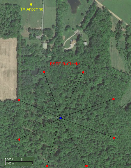
The primary receive antenna for 630M is a full sized BSEF (Broadside / End-Fire) 8-circle vertical array. Elements are positioned to provide 1140 ft (348m) of broadside spacing (0.55 wavelength) and 470 ft (143m) end-fire spacing. The total area encompassed by the array is approximately 25.2 acres (10.2 ha), requiring a square area of nearly 30 acres (12 ha).
 The optimal array RDF is calculated at 12.5 and the -3 dB beamwidth is 55 degress. Below are the azimuthal and elevation plots (MMANA-GAL):
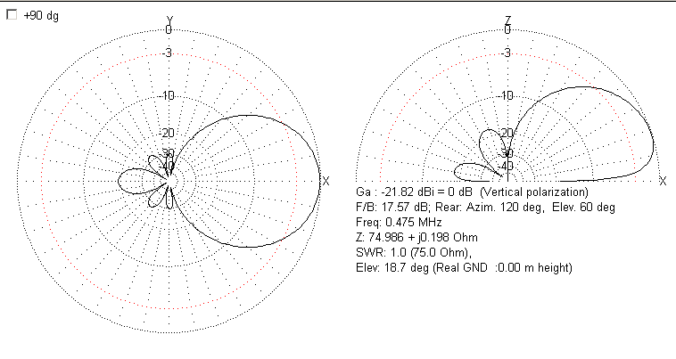
Background and Motivation
The BSEF 8-circle array has been popularized and used by the 160M weak-signal / DXing crowd. It consists of eight (8) short vertical elements (either passive or active) arranged around the circumference of a circle, with broadside spacing anywhere from 0.55 to 0.65 wavelengths typical. At any given time, only four (4) elements are used, an adjacent pair and their counterparts on the other side of the circle. These four (4) elements are then combined in such a way to produce a directional pattern, comparable to phased beverages. More information on short verticals and the BSEF array can be found at: http://www.w8ji.com/small_vertical_arrays.htm.
The motivation for this project was to ultimately experiment with a 630M-centric, high performance receive array design. I currently have a BSEF 8-circle array on 160M; this project is essentially a scaled up version of that array, though, somewhat closer broadside spacing in terms of wavelength. Element bandwidth was a particular challenge, but a simple method of over-swamping is used as described by ON4UN in his “Lowband DXing” book. The construction of this array has been a unique learning experience. This array also provides useful directivity to the Northwest (NW) and North (N), for which my 160M end-fire beverage arrays in those directions were not particularly useful on 630M.
Elements
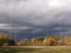
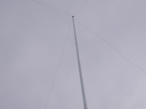
Vertical elements are constructed of four (4) 6-ft sections of 1 inch dia. aluminum tubing (24 ft height), joined by short pieces of 0.875 in. tubing and riveted. Top loading is accomplished with four 30 ft. wires (alum. fence wire), held in place with a stainless clamp. Top wires are tied off with fishing line, reducing element damage should a limb fall over any of the top wires (all elements are located in wooded areas; photo below is of a test element).
 A piece of 0.875 inch fiberglass rod insulates each vertical element. The fiberglass slides into and is bolted to a 12 inch piece of 1 inch tubing at the bottom, and the vertical element tubing at the top. The bottom 1 ft tubing section is clamped to an aluminum 1 inch angle, driven into the ground approx 2.5 ft (photo below is of a test element that used a steel angle and ground rod). A stainless bolt on the aluminum angle serves as the connecting point for the 12-16 radials (approx 60-75 ft long).
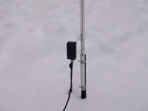
Tuning
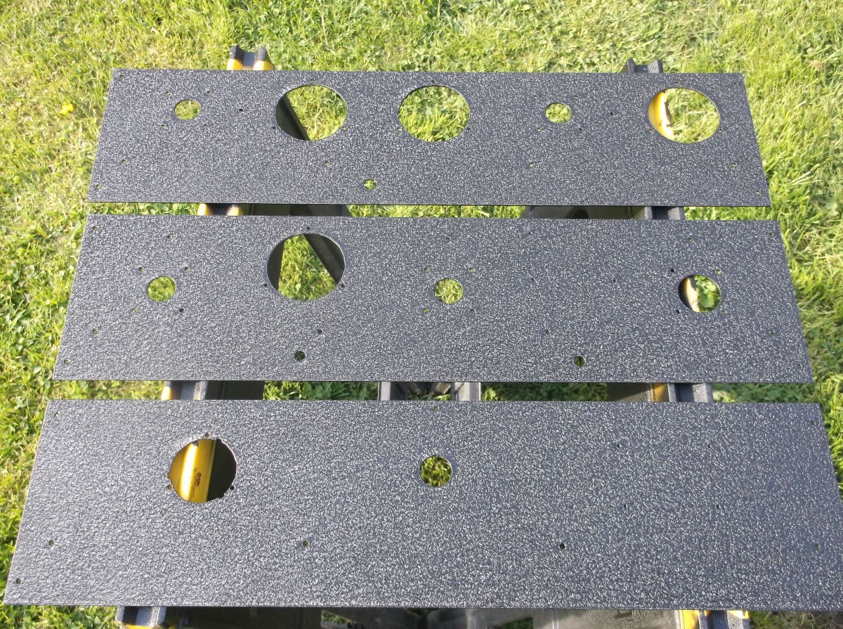
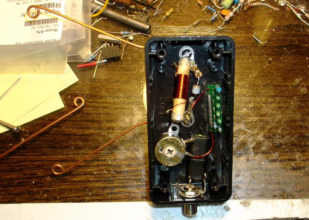
The boxes at each antenna base serve several functions, described below:
1. Gas discharge tube (90V) connected across the antenna and ground connections to mitigate potential buildup
2. Tuning to resonance is accomplished with a series combination of a homebrew, slug tuned coil (seen w/ red enameled wire below) for fine tuning and five (5) fixed inductors for course tuning: 390 uH, 22 uH, 10 uH, 4.7 uH, 2.2 uH. The fixed inductors are located on the small PCB, and each (other than the 390uH) can be bypassed by connecting a shorting block across the respective pins on a 0.1 inch header. (Note: the series potentiometer does add a very small amount of inductance change when adjusted)
3. Adjusting resistance is accomplished with a series 32 ohm potentiometer. The total resistance is brought up to 468-470 ohm with a series 300 ohm + 51 ohm film resistors (located on PCB) and approx. 90-95 ohm ground loss
4. Matching the 468-470 ohm feedpoint resistance to 75 ohm cable is done with a split winding transformer, wound as 4:10 turns Pri:Sec (6.25 impedance ratio) on a stack of two (2) BN73-202 cores. The additional core helps to increase common-mode suppression.
By “over-swamping” the feedpoint with additional resistance, the operating bandwidth is increased, which is important to ensure consistent phase relationships between all elements when using arbitrary, equal length phasing lines to the central phasing controller. An SWR of 1.15:1 or less is maintained over the 472-479 kHz operating range (1.2:1 SWR is typically 460-490 kHz for each element). The “over-swamping” method also helps to dampen the effects of ground loss changes, though, to what degree is yet to be determined until further measurements are conducted over the various seasons.
Phasing
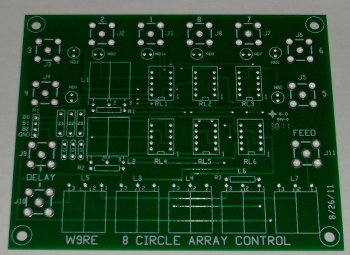
A W9RE designed 8-circle PCB is used for phase control at the center of the array. This design utilizes Magic-Tees to combine in phase elements, of which one pair is routed through a 180 degree transformer and delay cable. The delay cable is currently cut for 65 degrees at 475 kHz (approx 318 ft), resulting in a phase shift of 115 degress between front and back elements.
The feedlines from each element to the central phasing box are all approximately 700-710 ft long. After the first cable was installed, an analyzer was used to determine the quarter (1/4) wave frequency (X=0 with open end). That frequency was measured to be 291 kHz. All subsequent cables were cut to that electrical length to ensure a consistent phase relationship between all elements.
Direction Switching
Direction switching is accomplished via an NO3M designed control card. This device is remotely located about 600 ft from the shack and receives switching commands from a desktop controller via an RS-485 serial buss. Three (3) outputs from the control card are then routed to the central phasing box of the 8-circle array, which is another 600 ft away. The three (3) outputs allow selection of any eight (8) directions.
Performance
Information to be added.
Initial tests indicate a F/B of at least 22-28 dB, but is very dependent upon whether a station off the back is in one of the deeper nulls.
Below is an ARGO screen capture taken when switching between the Southwest (SW) and Northeast (NE) directions.
The signals from top to bottom are: WD2XSH/7 CW beacon in LA, WG2XKA (WSPR2) in VT, WG2XIQ in TX (WSPR2) and WG2XXM in OK (JT-9). It is clear to see when the direction is switched. Note the dog-boning of WD2XSH/7’s CW, which has a very faint trace when switched NE.
 Further data was collected using WG2XKA’s WSPR2 signal, 2014/03/03, switching between East (E) and West (W):
2336 -20 -0.1 0.475726 0 WG2XKA FN33 30
2342 9 -0.3 0.475726 0 WG2XKA FN33 30
2346 -20 -0.0 0.475726 0 WG2XKA FN33 30
2350 6 -0.0 0.475725 0 WG2XKA FN33 30
2356 -19 -0.0 0.475725 0 WG2XKA FN33 30
0000 5 -0.2 0.475725 0 WG2XKA FN33 30
0006 -18 -0.2 0.475725 1 WG2XKA FN33 30
0014 9 -0.3 0.475724 1 WG2XKA FN33 30
0022 -16 -0.1 0.475724 1 WG2XKA FN33 30
The above data shows a F/B range of 23 – 29 dB.
Bulk Materials
- RG6 Coax (Commscope F660BVV); phasing lines + delay cable: 5912 ft (1802m)
- 1 in. alum. tubing; elements: 192 ft (58.5m)
- #17 Fence wire; radials + top-hat wires: 7200 ft (2195m)
Future improvements and Modifications
-
Replace passive elements with hi-impedance elements using hi-impedance amplifiers to improve operating bandwidth, reducing potential phase errors over arbitrary length feedlines. Array will still be primarily an MF system due to broadside spacing.
-
More accurate element placement with hi-impedance elements to reduce spatial phase errors (top-loaded elements require some re-location due to inhibiting vegetation)
-
Attentuator pad on the non-delayed elements to equalize amplitude of front:back elements, maximizing null depth potential. Attentuation has not been measured through the 65 degree phasing cable at 475 kHz (cable length approx. 375 ft, RG6), so this is perhaps a moot endeavor
-
Implement an 8-circle variation using 0,-106,106 degree phasing where all elements are “active” simultaneously, smaller diameter circle (800 ft), better RDF (13.4))
Log
2014-03-09
The last two elements have been installed and connected into the system. Array construction is complete.
2014-03-01
Two (2) additional elements were added today. The array is now switchable NE, E, SW, W.
2014-02-28
Direction control has been added. Array can now be switched Northeast and Southwest
2014-02-24
Four (4) elements have been installed and connected to the central phasing controller. There is currently no direction switching, so array is fixed Southwest.
2014 Jan-Feb
Testing various mechanical variations of vertical elements, including all wire, various top wire lengths, tubing elements, passive element components, active element amplifiers, et.al.