630M Station
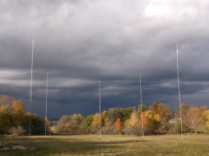
630M Receive Antenna (8-circle BSEF array)
Before the band was opened for Amateur use, I operated under a Part 5 experimental grant using the callsign WG2XJM starting in late 2012. Prior to getting my own Part 5 grant, I operated under the ARRL 600M Experimental Group grant as WD2XSH/46.
My current activities focus on 630M running CW and JT-9. Occasionally I will use other modes like SSB, WSQ, etc. I am no longer active under the WG2XJM Part 5 grant.
Transverter
A linear transverter is used in conjunction with an Elecraft K3 for all-mode 630M operation. The transverter is based on boards designed by VK3XDK. A 10 MHz GPSDO source provides the transverter LO as well as disciplining the K3 (K3EXREF).
 Two (2) VK3XDK transverter boards are used, one populated with parts for both transmit and receive, the other, receive only. Two (2) W1GHZ T/R PCBs are used for routing the main transverter board’s IF port to the K3’s separate TX and RX IF ports and for switching +Vcc during transmit.
The ADE-1 mixers (Level 7 / +7 dBm) originally on the VK3XDK boards where replaced with high-level ADE-1H mixers (Level 17 / +17 dBm). To provide adequate LO drive, the incoming 10MHz source is routed to a custom amplifier PCB (NO3M design), consisting of a SV1AFN based 2N5109 amplifier circuit, 10 MHz LPF, and a 0 degree hybrid splitter (Mini-Circuits LRPS-2-1). Output at each splitter port is approximately +17.5 dBm into 50 ohms.
Misc. Equipment
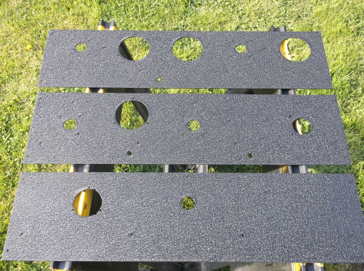
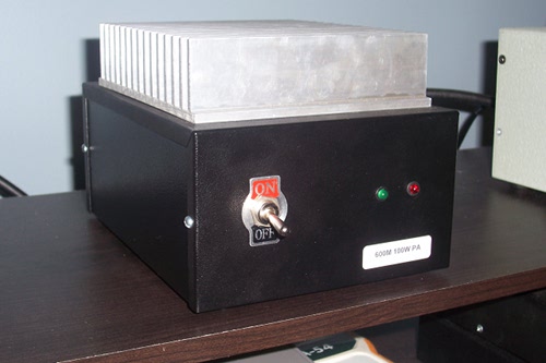 Modified EB63A linear amplifier based on mods by KN8AZN. LMB Heeger Tite-Fit chassis.
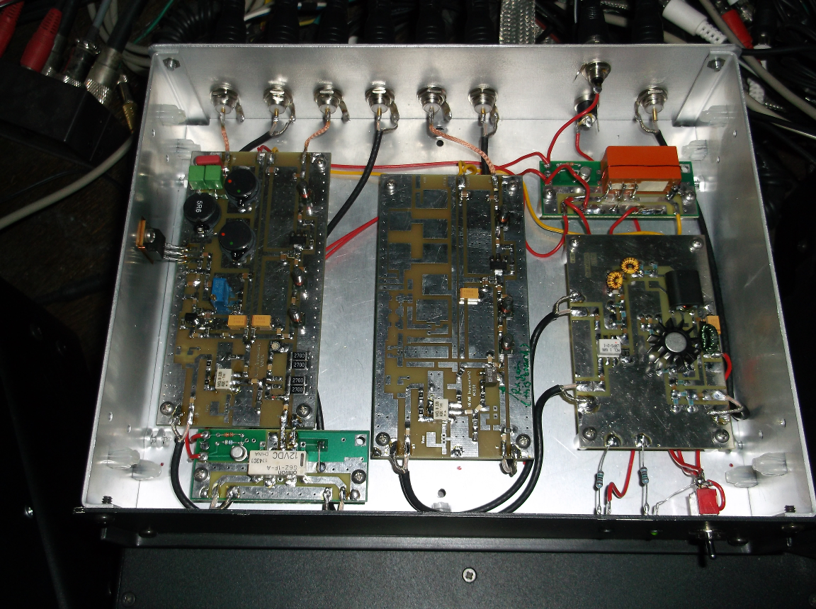
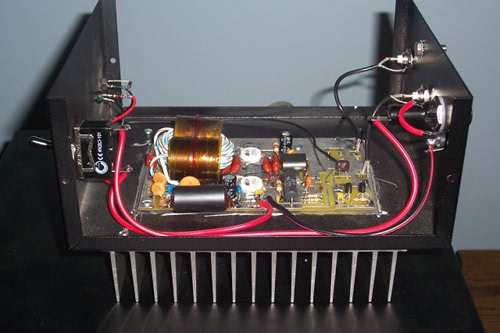 Inside of modified EB63A linear amplifier. COR circuit in original EB63 design is only used for a front panel “TX” LED.
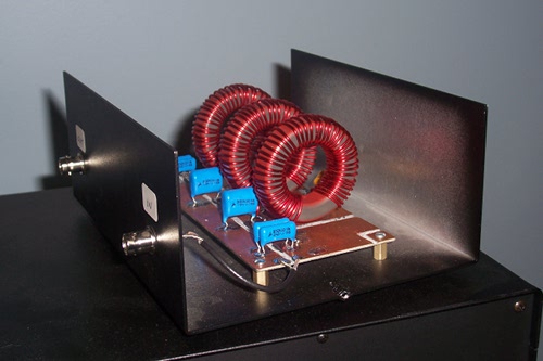 KN8AZN-design Elliptic LPF; T200-2 cores, Ten Tec enclosure.
SB-1000 Amplifier
THIS AMP IS NO LONGER USED UNDER AMATEUR OPERATIONS AND IS ONLY HERE FOR HISTORICAL PURPOSES
A modified Heathkit SB-1000 linear amplifier (3-500Z) is used for operation up to the Part 5 grant (WG2XJM) power limit of 100W ERP. Modifications include:
- Input Pi-network; 10000pf, 20.8uH, 7400 pf (Q=2.5 @ 475 kHz)
- Filament choke; FT240-77 core, 24T bifilar #14 enameled wire – 1.7 mH
- Plate Choke; #30 enameled wire over a 1″ x 6.75″ ceramic insulator – 1.13 mH
- DC supply bypassing capacitors (cold end of plate choke); 2 x .0047 uF 6kV
- Replaced DC Blocking capacitors, 2 x .002 uF 6kV
- Output Pi-network inductor; T300A-2 toroid, 69T #14 enameled – approx. 108 uH
- Additional padding capacitors in parallel with both the plate and loading air variables.
Output pi-network Q is approx. 14 @ 475 kHz and 13.4 @ 495 kHz. The amplifier is run at about 300W output to reach the 20W ERP level. Output power starts low for the first several seconds as the plate tuning padder capacitors (upper left in photo) start to warm up from RF current and drift in capacitance until they settle. Currently the padders are 2 x 500 pF 5kV HEC 858 (HT58) doorknobs, 2 x 170 pF 5 kV HEC 850 (HT50) doorknobs. The 500 pF padders may be replaced when more suitable caps are acquired (probably 10 x 100 pF 5kV HT50s) to reduce or mostly eliminate the capacitance drift by distributing RF current over more caps and better temperature coefficient in the lower value, HT50 series doorknobs.
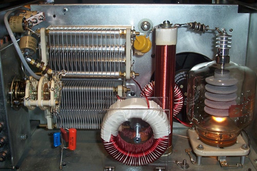 Inside the modified SB-1000 linear amplifier.