Receive Antenna Signal Processor
The signal processor is used in conjunction with the desktop controller, but has been designed to also be a standalone unit. A header connector on-board can be used to wire front-panel switches for manual control of the unit. An LCD is used to provide system feedback, including filter selections, band, antenna selection, net system gain, radio assignment, and COR or PTT activation.
An on-board embedded MPU, receiving commands from the desktop controller via an RS485 serial buss, provides the appropriate automated control of the processor’s sub-systems (if not using manual switches):
- Signal source: RX switching system or TX Ant (from radio’s RX-OUT) selection
- Impedance transformer (75 -> 50 ohm) on/off
- Chebyshev BCI High Pass filter on/off
- W3NQN modified design Bandpass filters (3 slots available) or bypass
- (2) IK4AUY based preamplifiers (+13dB gain, +43dbm OIP3)
- 31 dB step attentuator, 1dB resolution (automatic compensation for upstream splitting losses when splitters are engaged)
- Auxillary output routing (used for routing or splitting signal to NCC phase controller), which can be looped back to processor and routed to receiver
Other addition sub-systems include:
- Carrier operated relay – activates on signal overload, can open signal line or insert attenuation
- PTT detection – opens signal path if PTT signal is provided from TX; handles open collector or TTL input
- Component area for implementaion of one of various diode based limiters, incl. similar to ICE 196 (others: IK4AUY w/ zeners, traditional back-to-back IN914s) – not currently used in units here
- Simple command protocol via serial (RS-485 or RS-232) to control sub-systems
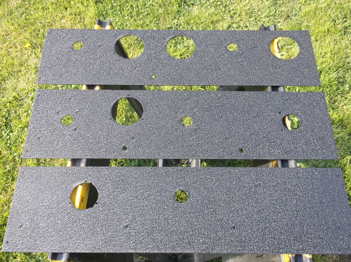
 Signal Processor, Front View
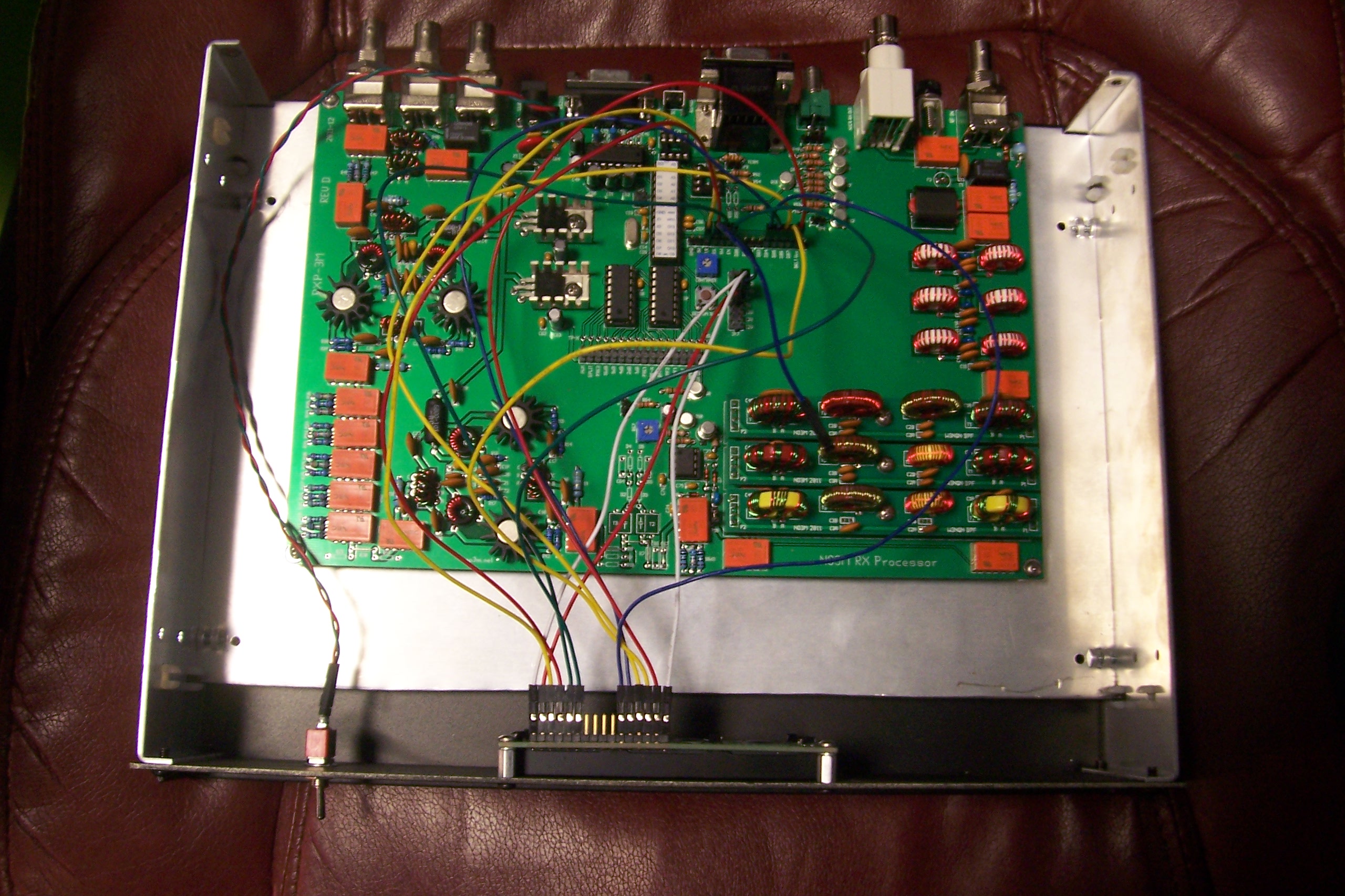
 Main PCB
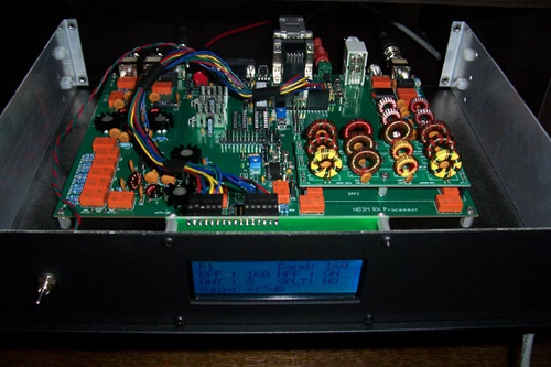
 Inside View
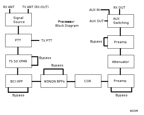 Functional Diagram