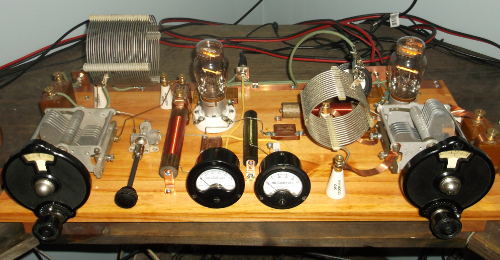
160M 1928 MOPA
1928 160M MOPA running a 210 (10Y) Hartley oscillator and 210 (10Y) neutralized amplifier. Maximum output 15-16W when fully loaded. The oscillator runs off of a 350V plate supply (with “Slop Jar” / Mason jar rectifier) and the amplifier from a 550V supply. Filaments (7.5V) are tied together and both stages keyed through a “center-tap” resistor (pair of 47 ohm metal film). Homebrew RF chokes in the plate leads are used (#32 enameled wire, 15/16 in. dia., 3 in. length; 770uH) and between the amplifier grid and grid leak resistor (#30 enameled wire, 7/16 dia., 2 in. length, 250uH).
 (click to enlarge)
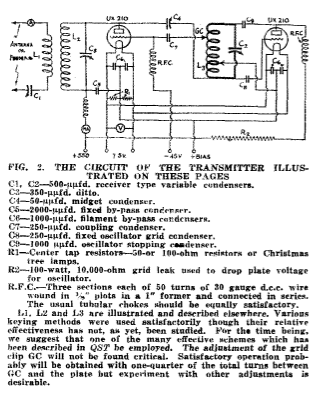
The design is based off of a September 1928 QST article by Ross Hull, “The Oscillator-Amplifier Transmitter“. Some changes include the use of capacity coupling to the antenna from the amplifier tank (instead of inductive link coupling), no amplifier grid bias voltage (grid leak directly to ground), and neutralization is done from amplifier tank (double-ended) to amplifier grid (Hull’s used oscillator tank to amplifier plate neutralization, but any changes in oscillator tank taps require re-neutralization).
With adequate excitation from the oscillator, the 10K amplifier grid-leak develops enough voltage drop (12mA current = -120 V) to put the amplifier into Class-C operation. Overall efficiency is on the order of 55-60%. A period National vernier is used for tuning reduction on the oscillator tuning capacitor.
Amplifier Tank Output Taps
The following table shows the measured power input and output, amplifier plate voltage and current, and amplifier efficiency with different ground and antenna taps on the amplifier’s plate tank coil (57uH). All tap positions are referenced from the end of the coil opposite the tube plate connection.
With this particular tank coil, efficiencies are best with 2 turns between the ground and antenna taps (reflecting the best “50 ohm” position on the coil with reference to the ground tap and plate impedance). However, with the 6-9 (ground/antenna) tap combination, a respectable efficiency of 52.8% with an output power of 23 W is achieved.
Currently, the actual ground tap is set at the 6 turn position, with the antenna tap adjusted to either the 8th or 9th turn depending upon how much power input/output is desired.
| GND Tap | ANT Tap | Pout (W) | Voltage (V) | Current (mA) | Pinp (W) | Eff. (%) |
|---|---|---|---|---|---|---|
| 5 | 7 | 0 | 0 | 0 | 0 | 0 |
| 5 | 8 | 0 | 0 | 0 | 0 | 0 |
| 6 | 7 | 2.9 | 585 | 12 | 7.02 | 41.3 |
| 6 | 8 | 12.5 | 572 | 41 | 23.45 | 53.3 |
| 6 | 9 | 23.0 | 558 | 78 | 43.52 | 52.8 |
| 7 | 9 | 14.25 | 568 | 46 | 26.13 | 54.5 |
| 7 | 10 | 24.8 | 555 | 88 | 48.84 | 50.7 |
| 8 | 10 | 16.0 | 566 | 51.5 | 29.15 | 55.0 |
| 8 | 11 | 27.0 | 550 | 96 | 52.8 | 51.1 |
| 9 | 11 | 17.4 | 564 | 56 | 31.58 | 55.0 |