Receive Antenna Switches
Background
The switch module is the core of the antenna routing and distribution system. It provides the ability to route a single antenna input to any of four radio outputs. By inter-connecting the radio ports of multiple switch modules, multiple antennas are made available to each radio port. This clustering of switch modules essentially creates a multi-port, 4 radio antenna switch.
Design
The overall design of the switch module was inspired by the W7IY switch board. However, it eventually evolved to include various enhancements adding additional functionality, eliminating external component dependencies, and providing a more flexible and robust control methodology.
The first enhancement was to include a switchable termination; the connected antenna can be left open, or terminated to ground or it’s characteristic impedance when unused. In general practice, a termination is not needed, but for some types of antennas, like switchable-direction beverages, the option is available to terminate the unused connection to 50 or 75 ohms.
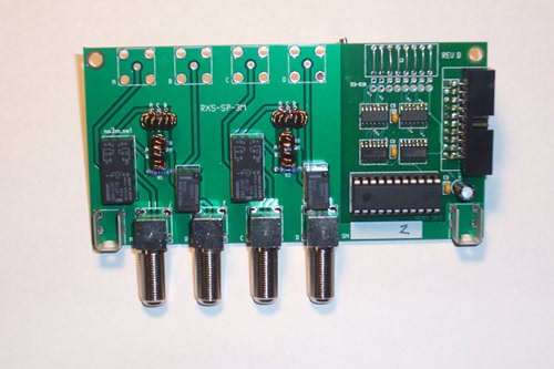
The next enhancement was to include an onboard splitter, eliminating the need for an external splitter. The splitter is used to share an antenna between any two “opposite” radio-receiver radio ports, meaning, it can be split between 1 or 2 and 3 or 4. The onboard splitter is based on the commonly cited “Magic-T” using FT37-43 cores. Isolation between splitter output ports was informally measured on the order of 30+ dB on the lowbands with splitting losses between 3.1 – 3.4 dB, dpending upon the band. A trifilar wound impedance transformer on the same type core is used to preserve the system impedance on the antenna port. Small signal relays are used to switch-in or bypass the splitter.
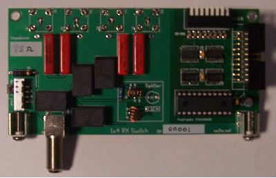
Standard F connectors were used on the switch modules to accomodate the connection of antenna and radio coaxial feeds. F connectors are generally considered standard for use in receive only applications when interconnecting with CATV coax (ie. RG6, RG11, etc.).
The last and most substantial enhancement was the control logic section. The basic concept is that a microcontroller module connects to all the switch modules in the same chain via a parallel data buss using 20-conductor ribbon cable. The microcontroller latches an 8-bit address as well as 8 bits of data over the buss to control the relay switching of the respectively addressed switch module.
The relay driver design is still based on the Micrel 58P01 parallel-data sink-latching IC like the W7IY system, but the addressing circuitry is arranged to provide full binary address assignment. With 8 available bits, this can accomodate up to 254 devices (`0` is not used) on the same data-bus. While this is impractical due to the fact the remote controller module is providing the 5V power to each switch module in the chain, it does allow for a few extra devices beyond eight, which would be the limitation of single bit addressing. The extra logic used in the addressing section also prevents the potential for a short circuit condition if more than one address bit is set, unlike the single-bit addressing method.
Switch Matrix
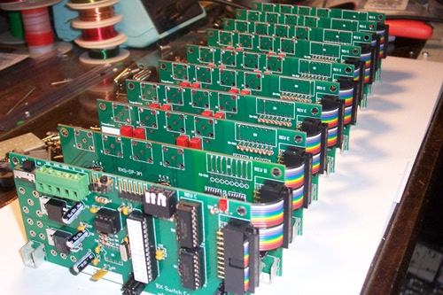
Ultimately, a series of individual switch modules and a single remote controller module are interconnected to form a complete remote switchbox. Similar radio ports between switch modules are connected in parallel using bare copper wire. An early prototype started out with using RG-174 mini-coax between switch boards, but it became quite time consuming and tedious. Using bare, unshielded copper was quick, easy, and based on isolation tests, sacrificed no significant amount of isolation between radio ports.
Additional Splitting
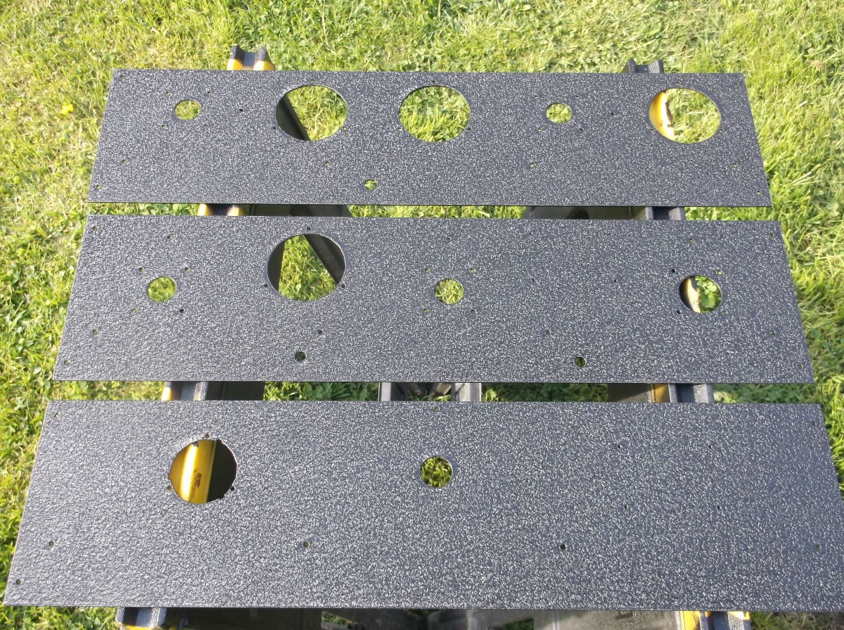
An additional splitter board is added to the end of the chain of boards. This additional board terminates each of the four radio port lines and provides additional splitting whereby any receiver can share an antenna, including adjacent receivers (ie. 1 and 2 or 3 and 4), which may be receivers within the same radio. This provides the ability for any or all of four receivers to acquire any of the available antennas. The termination board also brings the radio port lines out at the bottom of the board via F connectors to keep consistent w/ the rest of the individual antenna switch boards, so all coaxial connections are facing the same direction for mounting in an enclosure for outdoor use.
Expansion
The basic switching box provides up to 8 antennas, however, in large systems, more are required. To accomplish system expansion, modified switching boards (without onboard splitters) are used in reverse, ie. four inputs to one output. The inputs connect to the 8×4 switching units, while the single output routes back to the shack (or more intermediate routing boxes). This method of expansion provides the ability for virtually unlimited antennas available to 4 receivers, realistically the only limit is in the software or master hardware controller implementation (memory required to store antenna configurations).