Receive Antenna Switching System
Background
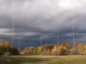
After the initial installation of the beverage antennas in 2010, a simple single-feed, six posistion switch was used to select the desired beverage antenna. This switch was based on a modified “bugcatcher” coil tap PCB obtained from FAR circuits, purchased when experiementing with Bugcatcher antennas in mobile operation. It never worked very well in that application, but was a quick option and seemingly adequate solution for the initial beverage switching. The switch board used generic Radio Shack relays and was controlled using a retired Sixpack switchbox over CAT-5 network cable.
Following operations in the 2010/2011 160M contests (ARRL160, Stew Perry, CQ160), it became evident that an improved receive antenna switching system was needed. The simple switching system only provided a single radio feed, which was split at the shack to feed the sub-receivers of both K3s. The NE beverage was not connected to the switching system and was split and fed to the main receivers in both K3s. While this scheme worked relatively well, it would have been beneficial to have the ability to switch any beverage to any reciever in either radio, especially when propagation is shifting towards the west during early morning hours.
Design Goals
The design goal for the new receive antenna switching system was simple: provide a flexible and reasonable number of receive antenna inputs to all four receivers (main and sub in both radios). While the goal itself was simple enough, implementation of such a system was certainly not. Receive antenna distribution is greatly complicated by the fact that the antennas are typically shared between receivers. Off-the-shelf antenna switches intended for transmitting do not provide the ability to properly share antennas between radio ports, as they lack any kind of isolation splitter and impedance preservation. This can lead to severe signal depravation to a given receiver due to potential differences in source impedance of the receivers attached to the same antenna. Additional goals that developed later were the ability to remotely mount and control the antenna switches to reduce the number and amount of coax needed to the shack, and a comprehensive gain distribution and compensation system to equalize gain differences between all receive antennas.
Existing designs
While there are several published beverage switching systems on the Internet, both homebrew and commercial, all designs are bound by a limitation on the number of available antenna ports. These limitations are either a result of hardware or software deficiencies. The design that appeared to have the most potential, and subsequently the basis for my own system concept, was that of Stu Mitchell, W7IY, (https://www.stu2.net/projects/bev2/). His switching system is unique in that antenna distribution is accomplished using a modular approach, which ultimately provides the ability for extensive expansion of the number of potential antenna ports. However, in it’s current implementation, there is still a limit based on the software and 6-postition control heads.
Evolution
It quickly became evident that there was no existing solution to meet the design goal of an essentially boundless switching system. It may be questioned at this point whether a “boundless” system is really needed. It’s been echoed in countless places, by countless amateurs, that one can never have too many antennas. This is especially true with receive antennas, as conditions on Topband are so variable, even in the course of one evening, that different antennas in the same directions could result in observable differences in signal reception, intelligibility, etc.
As previously noted, the W7IY design was the most interesting in concept and became the starting point for the initial design process. Correspondence with Stu on his design resulted in additional documentation, schematics, and PCB design files.
System components
The resulting receive distribution system is based on several components, each providing the necessary functionality to meet the design goals. Some components were necessitated by the inclusion of others, for example, BCI high-pass and bandpass filter modules were soley included in the system based on reducing the exposed signal spectrum to the preamplifiers, reducing the potential for IMD problems.
Each system component is given it’s own treatise via the following links: