NO3M

Amateur Radio

Category: Vintage (page 5 of 8)

1934 Superhet Receiver #1

After doing a fair amount of building transmitters over the past couple of years, I felt it was time to finally dive into a receiver project.  I’ve built a few simple regens, but I wanted to try something more elaborate and that could at least have a fighting chance in crowded band settings like Field Day, et.al.

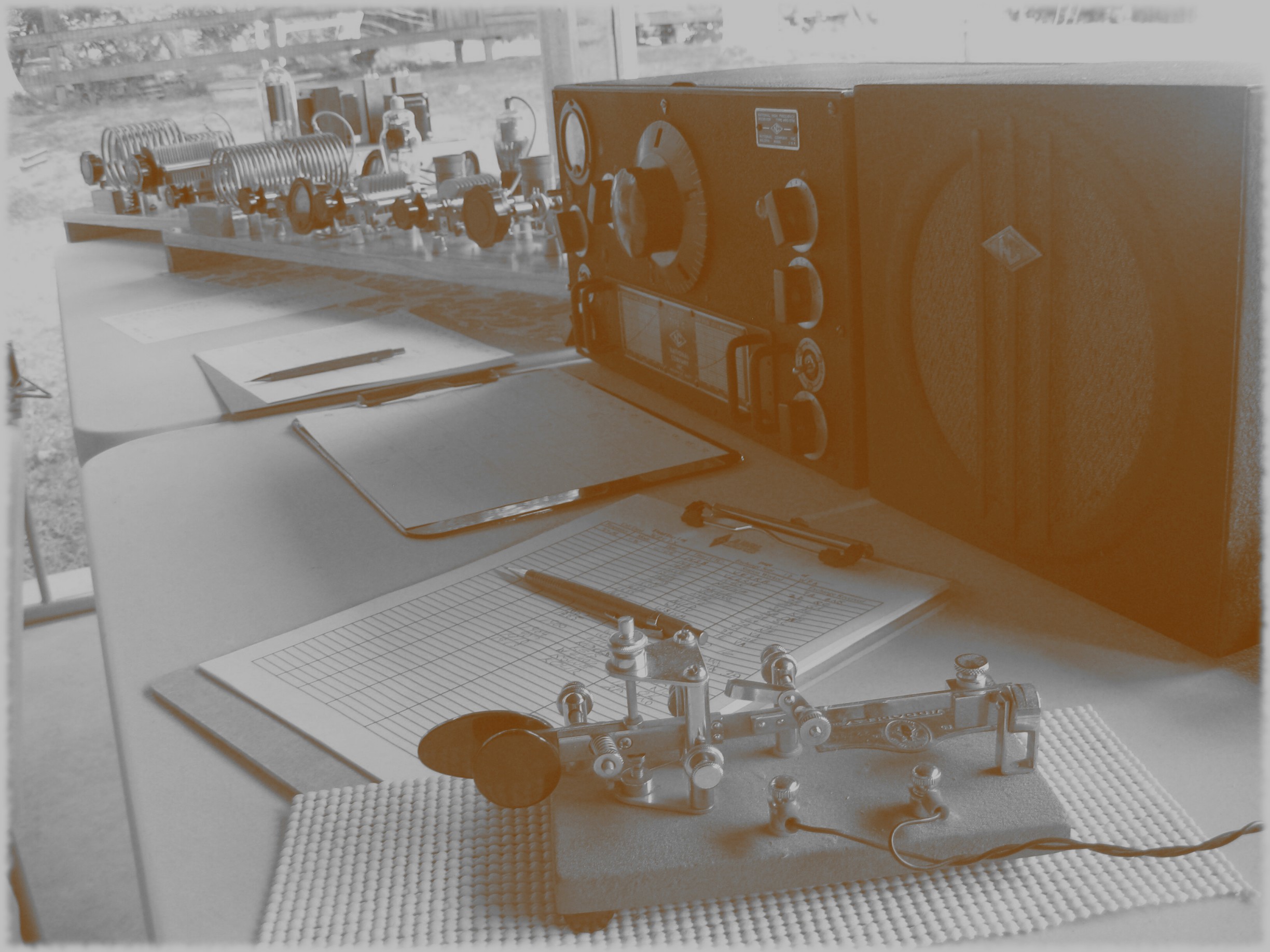
After comparing the performance of my National HRO-5TA1 and National SW-3 during our recent 1930s Field Day operation, it was clear a “single-signal” (S.S.) superhet would fit the requirements.  Some form of increased selectivity in the IF chain would be needed.  Back in the 30s, either a regenerative IF amplifier or crystal filter was used to accomplish the needed “single-signal” selectivity.  I chose to use a crystal filter and base the receiver on an article in May 1934 QST, “A De Luxe Crystal Type S.S. Receiver” by LeRoy Moffett, Jr., W9IJ.

may-1934-schem

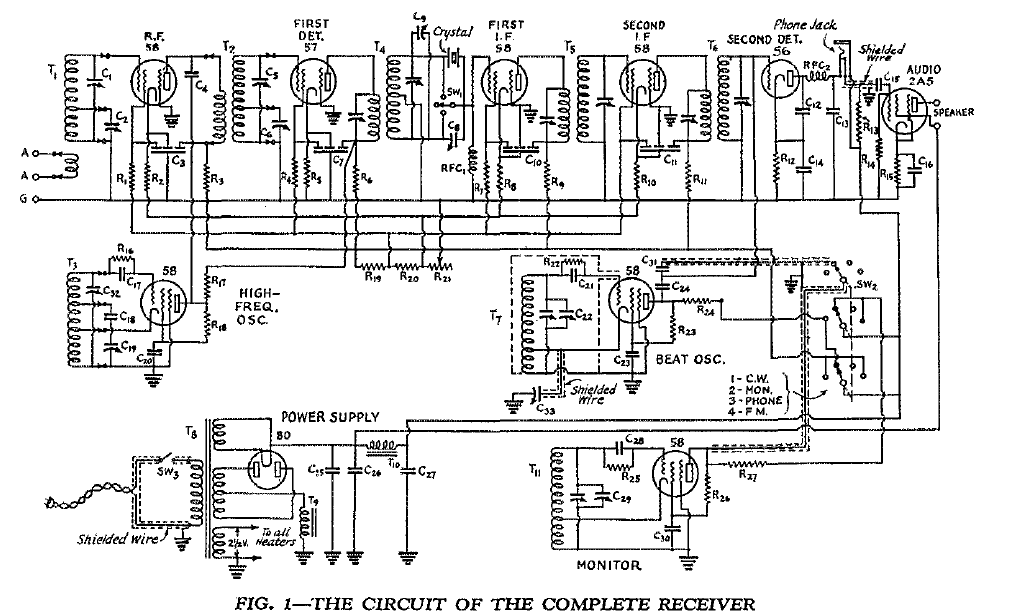
The receiver design described in that article is basically the quintessential circuit of the time, other than the monitor portion, and similar receivers Continue reading …..

W8CDX 1930s FD Setup at NO3M

FD-W8CDX-by-wa3tts

I had been tossing around the idea of doing an antique FD (Field Day) setup this year after having a lot of fun running my 1920s replica transmitters during several of the recent 160M Stew Perry (TBDC) events.  Once I committed to the idea by inviting several friends out for Saturday afternoon, I knew it was time to get busy, as I did not even have a transmitter built for 40M yet and it was about a week and a half before the FD weekend!Continue reading …..

Electrolytic Rectifiers

Before tube rectifiers were readily available, electrolytic rectifier banks (Slop Jar rectifiers) were common.

electrolytic-rectifiers-swpt-1921-qst

There is numerous literature in old QSTs on the construction, use and care of these type of rectifiers:

“A Symposium on Aluminum Electrolytic Rectifier Operation”, June 1922 QST

“Operating Notes on Electrolytic Rectifiers”, Sept 1921 QST

“An Electrolytic Rectifier for C.W.”, Feb 1921 QST

I chose to use a solution of distilled water and Sodium Bi-carbonate (Baking Soda), which works just as well as the more popularly referenced Sodium Borate (Borax).  A 385-0-385 volt Thordarson power transformer was used during initial testing, each side of the high voltage winding connects to a bank of eight (8) jars, C.T. (center tap) “grounded”.  No smoothing filter has been setup yet, but the output of the rectifier bank shows 400VDC on the voltmeter.  Once a suitable permanent setup is built for the transformer and filtering components (Stancor swinging choke and 20uF oil capacitors), this rectifier will be part of a B+ supply for several of my 1920s reproduction rigs.

no3m-electrolytic-rectifiers-1

Older posts Newer posts

© 2024 NO3M

Theme by Anders NorenUp ↑