I recently started a new receiver project, based in large part on the work by PA3AKE (https://martein.home.xs4all.nl/pa3ake/hmode/receiver_intro.html). Initially it will be an all analog design, but perhaps later incorporate DSP in at least the audio domain, perhaps in the IF as well.
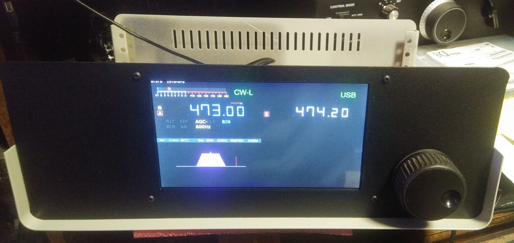
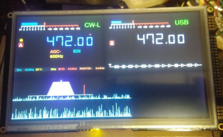
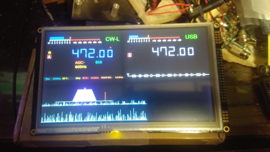
Early development for the rig’s display was done with a 3.2 in. TFT, but I decided to use something larger for more screen space. In addition, it would be more aesthetically pleasing, since the intended chassis / enclosure’s front panel is relatively large (14 in W x 5 in. H). A “tiny” screen would look a bit out of place on such a large amount of front panel real estate.
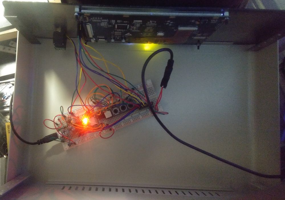
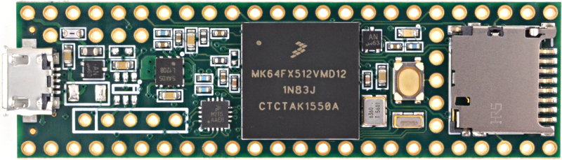
A 7 in. 800×480 pixel TFT display using a RA8875 driver (ER-TFTM070-5) was acquired from BuyDisplay.com. The rig’s microprocessor is a Teensy 3.5 (ARM Cortex M4), with the project’s code developed using the Arduino IDE.
One thing that came up while working out the display layout was effectively rendering the VFO readout. Early methods resulted in awkward and jerky display updates. Keep in mind that the entire program is running out of the main program loop, ie. single threaded. Multi-threading may provide smoother overall operation, but that is yet to be explored. For this particular implementation, any VFO frequency display updates are blocking the program execution and the routines need optimized for speed.
What not to do…
- Don’t use bitmap font rendering: rendering text using a bitmap font on graphic displays is sloooow! This is the case regardless of the display library and font geometry (discussed later…). Through benchmark testing, it was found that the optimal speed that could be achieved when changing a single digit in the frequency readout using a 50 pixel height font was about 7ms. Larger fonts are worse. That may not sound like much, but when shuttling along at a fast rate (2-3 RPM), it consumes a significant amount of time pausing the program flow while the shaft encoder continues to accumulate counts (via hardware interrupts), resulting in less than pleasing readout transitions — more of a hopping effect.
- Don’t update after every frequency increment: when shuttling along at a high rotation rate (2-3 RPM), attempting to update the display readout after every increment exasperates the effects mentioned above. The program ends up spending most of it’s time dealing with display updates.
How to optimize…
1. Choose a “font” with simple geometric properties:
Geometric drawing operations on TFT displays are much faster than font rendering due to built-in accelerated operations in the hardware display driver. To exploit this speed, a font that has simple geometric properties is required, since we are limited to line drawing, rectangle fills, triangle fills, etc. Further, horizontal and vertical lines generally render fastest. All these considerations lead us to basically a block font as illustrated below:
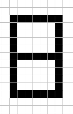
Not particularly attractive, is it? Since the font will need to be about 44 – 50 pixels high, each line will need to be about 3-4 pixels for the most aesthetic appearance, which can be rendered as rectangle fill operations. But, for perhaps a slight overhead, we can get a more styled font using line drawing. Remember the classic 7-segment LCD digits? This is a natural choice for a VFO readout given our restrictions for optimal rendering speed. There are still a number of rigs currently on the market not to mention boat loads of previous transceivers that used this type of digit font. Of course, before TFTs became popular in ham transceivers, this was done with generic or custom LCDs (ie. Elecraft K3). below is the basic 7-degment font:
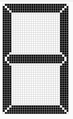
Using line draw operations to render the above 7-segment font reduced the a single digit update to 2.5ms! That’s 36% of the time required using a bitmap font of the same digits. But, we can improve this even further…
2. Optimize update routines to only apply differences: transitions between digits, sequential or not, often involve on average only a few segment changes. By comparing the previously displayed digit with the digit to be rendered, only the differences between the two need updated on the display, either transitioning from off to on, or visa versa. Updating in this manner further reduces single digit updates to 1ms!! That’s only 14% of the original bitmap font rendering time.
Is there anything else left to do?? You bet…
3. Limit display updates: there is no sense in updating the display every time the encoder counter is incremented (ie. frequency changed). Even with the significant reduction in rendering the digits, a lot of time would still be spent with display updates. Much like the frames-per-second refresh rate of a television, display updates can be limited to 20-30 times per second and still result in a “smooth” appearance when tuning at high rates (2-3 RPM).
Code example
Below are the snippets of code relevant to rendering the digits and controlling the refresh rate.
These functions will work with the Adafruit or sumotoy RA8875 libraries and have been tested with a 800×480 TFT and 400PPR rotary encoder. Additional features are leading 0 digit suppression (except less than 100 KHz) as well as suppressing the 1 MHz decimal. The 1 Hz digit is also suppressed unless the tuning step size is 1 Hz.
#define VFOA_COLOR ConvertRGB(67,128,249)
#define VFOA_TOP 100
#define VFOA_RIGHT 350
#define VFOA_DIGIT_WIDTH 40
#define VFOA_DIGIT_HEIGHT 46
#define VFOA_DECIMAL_WIDTH 15
#define VFOA_SMALL_DIGIT 8
#define VFOA_DECIMAL_HSHIFT1 227
#define VFOA_DECIMAL_HSHIFT2 92
#define VFOA_DECIMAL_VSHIFT 49
#define VFOA_DECIMAL_RADIUS 2
#define VFOA_LABEL_VSHIFT 29
#define VFOA_LABEL_HSHIFT 335

#define VFOB_COLOR ConvertRGB(180,180,180)
#define VFOB_TOP 100
#define VFOB_RIGHT 750
#define VFOB_DIGIT_WIDTH 40
#define VFOB_DIGIT_HEIGHT 46
#define VFOB_DECIMAL_WIDTH 15
#define VFOB_SMALL_DIGIT 8
#define VFOB_DECIMAL_HSHIFT1 227
#define VFOB_DECIMAL_HSHIFT2 92
#define VFOB_DECIMAL_RADIUS 2
#define VFOB_LABEL_VSHIFT 29
#define VFOB_LABEL_HSHIFT 335
#define TFT_BGLIGHT ConvertRGB(10,10,10)

#define NUM_VFO 2
#define VFO_REFRESH 40000

uint32_t vfo_update_us = micros();
uint32_t vfoFreq[NUM_VFO] = { 1800000, 1800000 }; // default
uint32_t vfoFreqLast[NUM_VFO] = { 1800000, 1800000 };
uint16_t vfoStepSize = 10;

word ConvertRGB( byte R, byte G, byte B)
{
  return ( ((R & 0xF8) << 8) | ((G & 0xFC) << 3) | (B >> 3) );
}

void dispVFO(uint32_t vfoOld, uint32_t vfoNew, int vfo, boolean refresh = false) {

  if (vfoNew == vfoOld && !refresh) return; // nothing to do

  byte digits[2];
  static const unsigned char nums[12] = {0x3F, 0x06, 0x5B, 0x4F, 0x66, 0x6D, 0x7D, 0x27, 0x7F, 0x6F, 0x00, 0x40}; // segment map
  byte s = (vfo) ? VFOB_DIGIT_HEIGHT : VFOA_DIGIT_HEIGHT; // digit height
  int i, j;
  uint16_t x, y, col;
  uint32_t vfoNew_tmp = vfoNew;
  uint32_t vfoOld_tmp = vfoOld;

  for (i = 0; i < 8; ++i) { // digits

    digits[0] = vfoOld_tmp % 10;
    digits[1] = vfoNew_tmp % 10;
    vfoOld_tmp /= 10;
    vfoNew_tmp /= 10;

    if (digits[0] != digits[1] || refresh) { // clear and update only if changed or forced

      for (j = 0; j < 7; ++j) { // segments

        if ( refresh || (nums[digits[0]] & (1 << j)) != (nums[digits[1]] & (1 << j))
              || (vfoNew < 10000000 && vfoOld >= 10000000) || (vfoOld < 10000000 && vfoNew >= 10000000)
              || (vfoNew < 1000000 && vfoOld >= 1000000) || (vfoOld < 1000000 && vfoNew >= 1000000)
              || (vfoNew < 100000 && vfoOld >= 100000) || (vfoOld < 100000 && vfoNew >= 100000)
           ) {

          byte s_tmp = s;
          if ( i < 3 ) {
            s_tmp -= (vfo) ? VFOB_SMALL_DIGIT : VFOA_SMALL_DIGIT;
            if (vfo) { // digit position
              x = VFOB_RIGHT - (i * VFOB_DIGIT_WIDTH) - ((i / 3) * VFOB_DECIMAL_WIDTH);
              y = VFOB_TOP + VFOB_SMALL_DIGIT;
            } else {
              x = VFOA_RIGHT - (i * VFOA_DIGIT_WIDTH) - ((i / 3) * VFOA_DECIMAL_WIDTH);
              y = VFOA_TOP + VFOA_SMALL_DIGIT;
            }
          } else {
            if (vfo) { // digit position
              x = VFOB_RIGHT - (i * VFOB_DIGIT_WIDTH) - ((i / 3) * VFOB_DECIMAL_WIDTH);
              y = VFOB_TOP;
            } else {
              x = VFOA_RIGHT - (i * VFOA_DIGIT_WIDTH) - ((i / 3) * VFOA_DECIMAL_WIDTH);
              y = VFOA_TOP;
            }
          }
          if ( nums[digits[1]] & (1 << j) &&
               !(i == 6 && vfoNew < 1000000) && !(i == 7 && vfoNew < 10000000) && !(i == 5 && vfoNew < 100000) && !(i == 0 && settings.vfoStepSize > 1)
             ) {
            col = (vfo) ? VFOB_COLOR : VFOA_COLOR;
          } else {
            col = TFT_BGLIGHT;
          }

          switch (j) {
            case  0:
              //a
              tft.drawFastHLine(x + 1, y    , ((s_tmp * 6) / 10)    , col);
              tft.drawFastHLine(x + 2, y + 1, ((s_tmp * 6) / 10) - 2, col);
              tft.drawFastHLine(x + 3, y + 2, ((s_tmp * 6) / 10) - 4, col);
              tft.drawFastHLine(x + 4, y + 3, ((s_tmp * 6) / 10) - 6, col);
              break;

            case  1:
              //b
              tft.drawFastVLine(x + ((s_tmp * 6) / 10) - 2, y + 4, (s_tmp / 2) - 6, col);
              tft.drawFastVLine(x + ((s_tmp * 6) / 10) - 1, y + 3, (s_tmp / 2) - 4, col);
              tft.drawFastVLine(x + ((s_tmp * 6) / 10)    , y + 2, (s_tmp / 2) - 2, col);
              tft.drawFastVLine(x + ((s_tmp * 6) / 10) + 1, y + 1, (s_tmp / 2)    , col);
              break;

            case  2:
              //c
              tft.drawFastVLine(x + ((s_tmp * 6) / 10) - 2, y + (s_tmp / 2) + 4, (s_tmp / 2) - 6, col);
              tft.drawFastVLine(x + ((s_tmp * 6) / 10) - 1, y + (s_tmp / 2) + 3, (s_tmp / 2) - 4, col);
              tft.drawFastVLine(x + ((s_tmp * 6) / 10)    , y + (s_tmp / 2) + 2, (s_tmp / 2) - 2, col);
              tft.drawFastVLine(x + ((s_tmp * 6) / 10) + 1, y + (s_tmp / 2) + 1, (s_tmp / 2)    , col);
              break;

            case  3:
              //d
              tft.drawFastHLine(x + 4, y + s_tmp - 2, ((s_tmp * 6) / 10) - 6, col);
              tft.drawFastHLine(x + 3, y + s_tmp - 1, ((s_tmp * 6) / 10) - 4, col);
              tft.drawFastHLine(x + 2, y + s_tmp    , ((s_tmp * 6) / 10) - 2, col);
              tft.drawFastHLine(x + 1, y + s_tmp + 1, ((s_tmp * 6) / 10)    , col);
              break;

            case  4:
              //e
              tft.drawFastVLine(x    , y + (s_tmp / 2) + 1, (s_tmp / 2)    , col);
              tft.drawFastVLine(x + 1, y + (s_tmp / 2) + 2, (s_tmp / 2) - 2, col);
              tft.drawFastVLine(x + 2, y + (s_tmp / 2) + 3, (s_tmp / 2) - 4, col);
              tft.drawFastVLine(x + 3, y + (s_tmp / 2) + 4, (s_tmp / 2) - 6, col);
              break;

            case  5:
              //f
              tft.drawFastVLine(x    , y + 1, (s_tmp / 2)    , col);
              tft.drawFastVLine(x + 1, y + 2, (s_tmp / 2) - 2, col);
              tft.drawFastVLine(x + 2, y + 3, (s_tmp / 2) - 4, col);
              tft.drawFastVLine(x + 3, y + 4, (s_tmp / 2) - 6, col);
              break;

            case  6:
              //g
              tft.drawFastHLine(x + 3, y + (s_tmp / 2) - 1, ((s_tmp * 6) / 10) - 4, col);
              tft.drawFastHLine(x + 2, y + (s_tmp / 2)    , ((s_tmp * 6) / 10) - 2, col);
              tft.drawFastHLine(x + 2, y + (s_tmp / 2) + 1, ((s_tmp * 6) / 10) - 2, col);
              tft.drawFastHLine(x + 3, y + (s_tmp / 2) + 2, ((s_tmp * 6) / 10) - 4, col);
              break;

            default:
              break;
          }
        }
      }
    }
  }

  // only update when crossing 1MHz in either direction
  if ((vfoNew < 1000000 && vfoOld >= 1000000) || (refresh && vfoNew < 1000000)) {
    if (vfo) {
      tft.fillCircle(VFOB_RIGHT - VFOB_DECIMAL_HSHIFT1, VFOB_TOP + VFOB_DIGIT_HEIGHT -1, VFOB_DECIMAL_RADIUS, TFT_BGLIGHT);
    } else {
      tft.fillCircle(VFOA_RIGHT - VFOA_DECIMAL_HSHIFT1, VFOA_TOP + VFOA_DIGIT_HEIGHT -1, VFOA_DECIMAL_RADIUS, TFT_BGLIGHT);
    }
  } else if ((vfoOld < 1000000 && vfoNew >= 1000000) || (refresh && vfoNew >= 1000000)) {
    if (vfo) {
      tft.fillCircle(VFOB_RIGHT - VFOB_DECIMAL_HSHIFT1, VFOB_TOP + VFOB_DIGIT_HEIGHT -1, VFOB_DECIMAL_RADIUS, VFOB_COLOR);
    } else {
      tft.fillCircle(VFOA_RIGHT - VFOA_DECIMAL_HSHIFT1, VFOA_TOP + VFOA_DIGIT_HEIGHT -1, VFOA_DECIMAL_RADIUS, VFOA_COLOR);
    }
  }

  return;
}

void setup() {

/* ... */

  dispVFO(0, vfoFreq[0], 0, true);
  dispVFO(0, vfoFreq[1], 1, true);

}

void loop() {

/* ... */

  if (micros() - vfo_update_us > VFO_REFRESH) {
    for (int i=0;  i < NUM_VFO; ++i) {
      dispVFO(vfoFreqLast[i], vfoFreq[i], i);
      vfoFreqLast[i] = vfoFreq[i];
    }
    vfo_update_us = micros();
  }