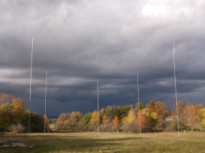
I recently started experimenting with a couple Lazy-H antennas for 10 and 15 meters. Dipole lengths are a little under 1 wavelength so as to maintain half-power points at approximately +/- 30 degrees (60 deg beamwidth). This maximizes gain while allowing a pair of them aimed 60 degrees apart to cover all of the contiguous US (180 – 300 degrees from WPA).
The Lazy-Hs are fed with ladderline in a distributed feed manner, ie. a length of ladderline is used to connect the upper and lower “dipoles” with NO TWIST, and the main ladderline feeder is connected exactly midway along the phasing ladderline. This maintains equal phasing vs. other feed methods which require attention to element lengths and spacing, and moreover are relatively single frequency methods.
The next question is one of which ladderline to use. Not having used much of any type of ladderline or open wire feeds to this point, there really wasn’t a particular decision made based upon experience. I had picked up some of the standard 450 ohm black “window” line from a previous hamfest, so initially that was used.
The results were promising, but any amount of moisture, ie. dew, rain, et.al., proved to be a problem when a nearly perfect match (1.02:1) on 21.130 MHz would climb to over 3:1 (almost every night).
A quest for a better alternative began, and after thorough research, I decided to homebrew some open-wire line.
Below is the process and materials used to build the OWL, which at the given spacing, would have an impedance of approximately 544 ohms. The impedance in this application isn’t critical.
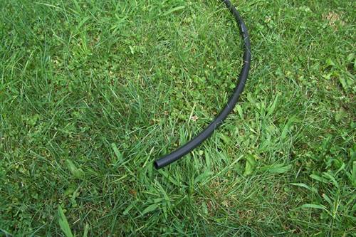
1/2 inch. poly drip irrigation tubing is used for the spacers. Cost approx. $40 for 100 ft. This will yield 320 spacers at 3.75 inch each. If spaced 18 inches along the transmission line, that will yield 480 ft of OWL.
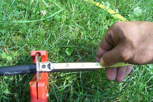
Further cuts are made by just lining up a previous piece, much quicker than measuring each one with a tape rule.
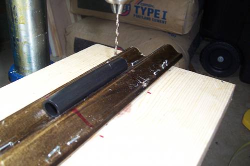
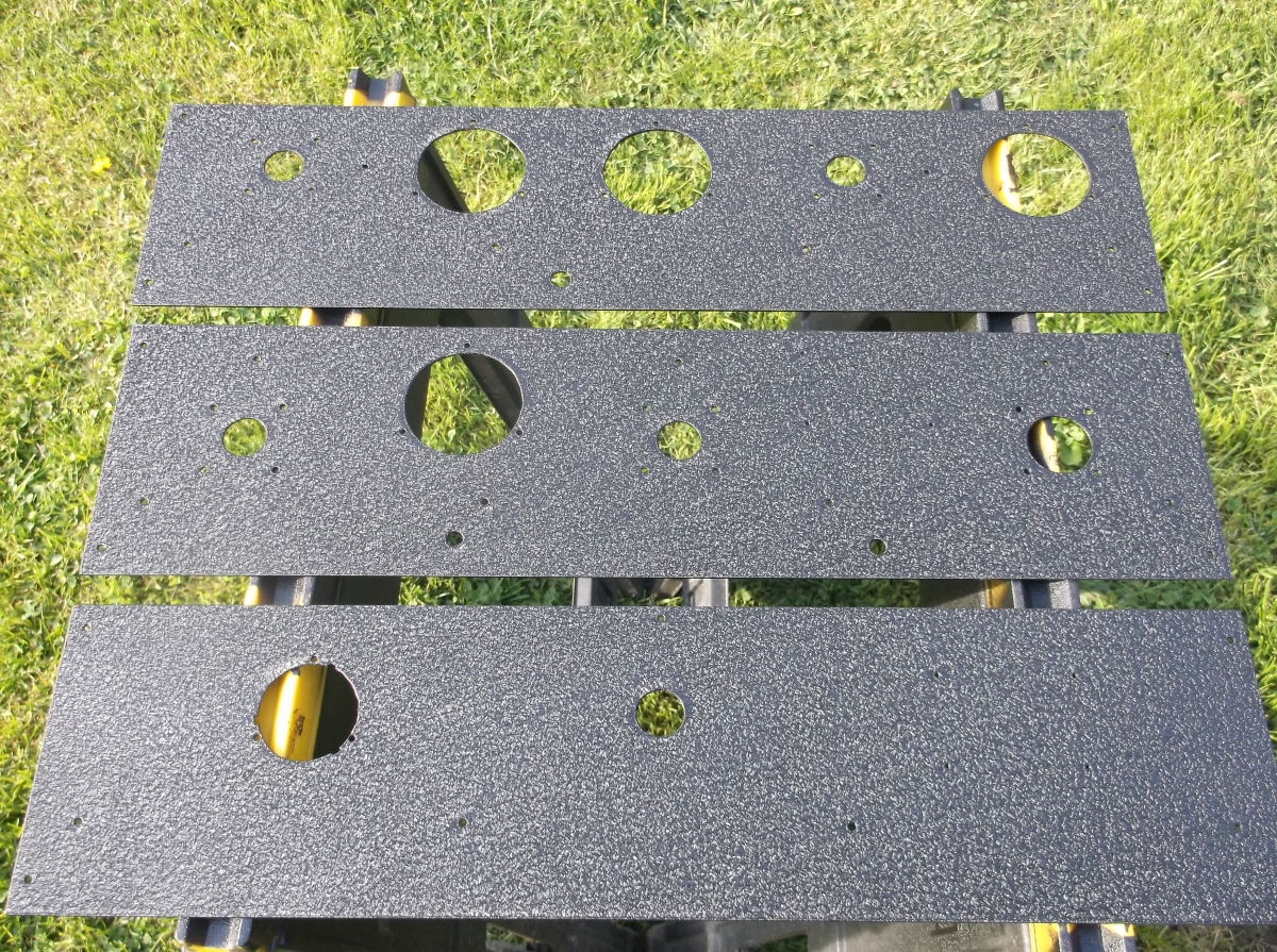
The tubing is in place and ready to be drilled.
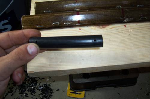
7/64 inch holes are drilled 3/8 inch in from the ends, this set the wire spacing at 3 inches. A 7/64 in. bit is slightly smaller than #14 THHN insulated wire, and when popped on, will create a “pinching” fit and not slide.
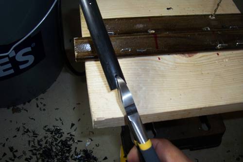 A pair of side-cutters are used to slit and notch the ends toward the holes. This will allow the spacer to be pushed onto the wires into the holes in the spacers.
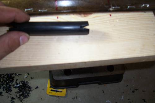
A close-up of the notches.
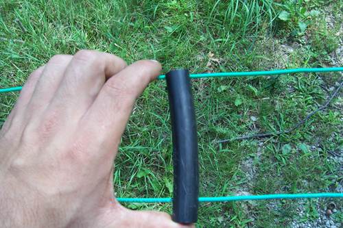
After pulling two wires taut between supports, each spacer is simply “popped” into the wire, that is, until the wire rests in the hole in the spacers. This method leaves the spacer very secure on the wire.
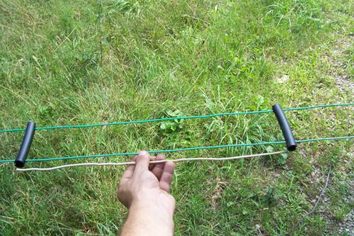
A heavy solid 12g wire was measured to 18 inches and used to maintain consistent separation between spacers.
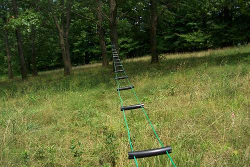
The finished line is ready to install.