I had been tossing around the idea of doing an antique FD (Field Day) setup this year after having a lot of fun running my 1920s replica transmitters during several of the recent 160M Stew Perry (TBDC) events. Once I committed to the idea by inviting several friends out for Saturday afternoon, I knew it was time to get busy, as I did not even have a transmitter built for 40M yet and it was about a week and a half before the FD weekend!
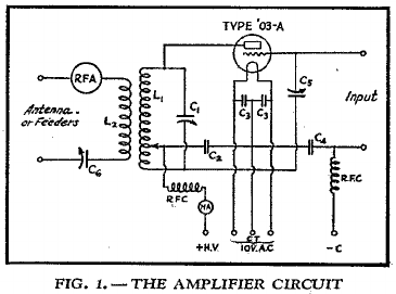
I starting going through some QST articles I had archived over the last year or so, attempting to find a suitable circuit for a 20/40M rig. The July 1931 QST (pg. 31) had an article entitled “Inexpensive Crystal Control, A Three-Band Low-Power Transmitter” that looked very promising. In the following month’s QST, a companion article, “Adding an Amplifier to the Low-Power Transmitter”, detailed an accessory amplifier for the transmitter project from the prior month using a 203A triode. This setup would probably be similar to what some Amateurs were actually running during the first Field Day event held in 1933. I felt confident this setup should do the job as long as it behaved, but I knew from experience that I had to get started right away to allow time for working out any “bugs”.
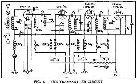 I set off building a test exciter, but in my initial version, decided to try a three-tube job instead of the four-tuber in the July QST article, leaving out one of the 224 doubler/buffer stages. I also substituted the 210 final with a 865 screen-grid tube to eliminate neutralization and changed the oscillator to a free-running Hartley tuned to 80M. Upon testing the finished lash-up, I was able to get about 8W out on 40M, but only 0.8W out on 20M when using the 865 as a doubler. There just wasn’t enough output from the preceding 224 doubler stage (tuned to 40M) to drive the 865 as a doubler. I then decided to go back to the original QST circuit, adding the second 224 stage. Everything had to be rebuilt on a new breadboard to accommodate the extra space needed for the additional doubler/buffer. At this point, I’ve got one week left until FD commences. Anything built from this point onward had to be in it’s final form!
Saturday afternoon (week before FD) I acquired the needed lumber for the exciter and amplifier baseboards. I started staining right away. By the next day I had all the necessary coats of varnish applied and was just waiting for everything to adequately dry. I didn’t start placing parts on either until Monday, at this point very much concerned with time. I had everything on hand to complete both the exciter and amplifier, except for a pair of variable capacitors (ehem, condensers!) for the doubler/buffer tanks that matched the style of those I already had on hand. Luck was on my side, however, as there were a couple Ebay auctions going on with Cardwell 424-Bs that ended Monday afternoon! These were exact matches for the variable capacitor I had for the 865 (final) tank. I knew the “must-have” attitude would come at a price, but I came away without too much of a dent in the bill-fold and two needed air variables! I sent the seller a private message asking if it would be possible to ship ASAP, he obliged. The package was dropped off Tuesday (Las Vegas) and made it here (WPA) by Thursday!
By the time the variable capacitors arrived, I had most of the exciter built, albeit untested. I could have thrown in a couple junkbox air variables, but decided to wait. I was also doing some construction here and there on the amplifier unit. When the capacitors arrived Thursday, I immediately dropped them in the exciter and commenced with some testing. With the additional 224 stage, I was getting about 10-11W out on 40M and 5W output on 20M. Great!
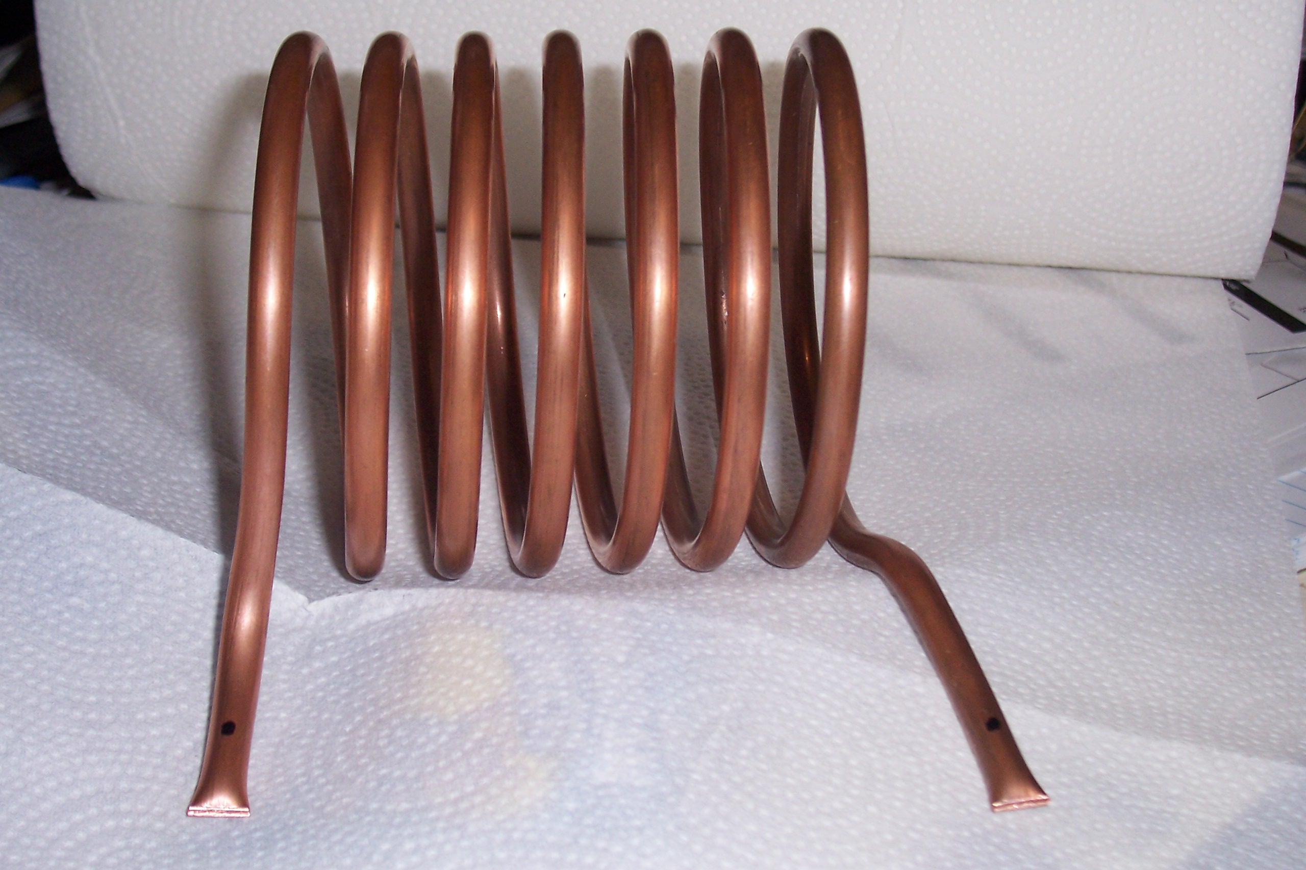
 I shifted my focus on to the 203A amplifier. By Friday evening, I had most of it wired up. The last bit was winding a copper tubing coil for 20M. I was having all sorts of problems with this one… tubing kinking while making the necessary tight bends to secure the ends to beehive insulators, drill bit grabbing one almost complete coil, ripping it from my grip tool and whipping it around like a toy, mangling it beyond repair. Frustration was really setting in. After the fourth attempt and some extra care, success! It was 1AM local time Saturday morning (yes, the day of Field Day)!
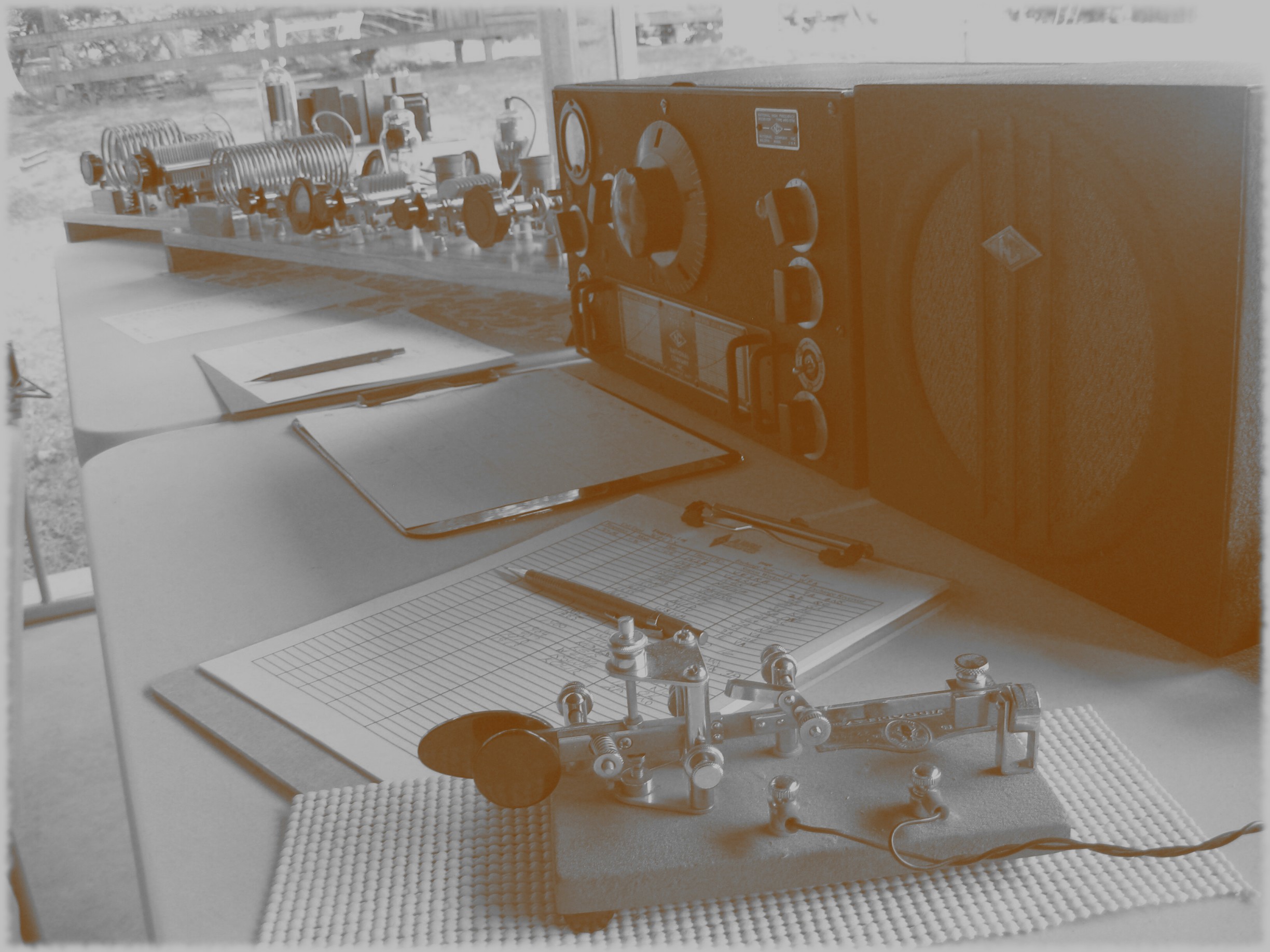
Fast forward to 2PM Saturday. I had lugged all the equipment up to the back porch an hour or so earlier, but nothing was hooked up except the HRO-5TA1 receiver humming away on 40M (post WW2 version, probably the most modern thing in the “shack” besides the digital clock hanging on the wall. The original HRO design can be traced back to early 1935, with mainly changes in the tube line-up over the years). At least we had the sweet music of 40M CW to listen to!
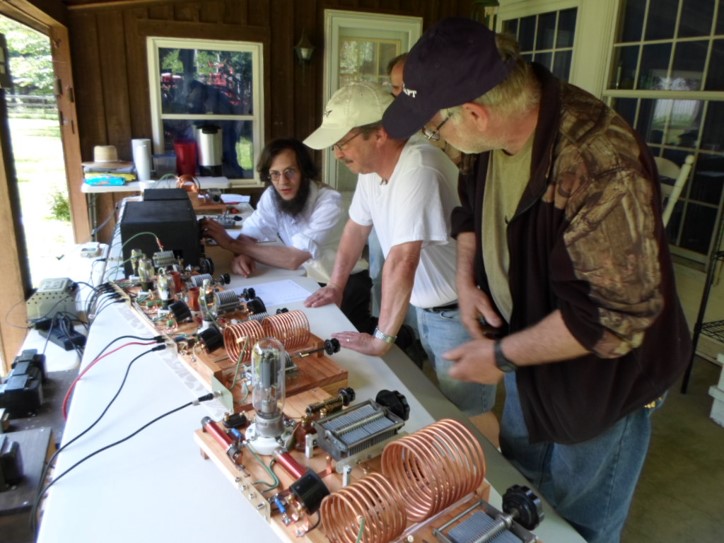
With a handful of guys already arrived, it was time to get this monstrosity on the air! I made quick to get all the cabling connected to the exciter and amplifier. Filaments lit, check. Power up the oscillator and doubler/buffers, all good. Quick signal check, sounds good. Power up the exciter final, done. For the first run, we just ran the exciter straight to the link-coupled, balanced tuner. Within a handful of minutes, we logged our first string of QSOs running about 10W output. Everyone was elated! However, at the same time I was quietly reserved about how the 203A amplifier would behave, having up to this point never been powered up! I worried about it breaking out into oscillations and all sorts of ill-mannered behaviors.
Here we go… the first order of business was neutralizing the 203A. Once we had the exciter and amplifier units connected up, we applied some signal from the exciter while using a small loop of wire and low-voltage pilot light to monitor RF in amplifier’s tank. A quick twist of the neutralizing cap, some re-tweaking of the tank tuning, another small adjustment of the neutralizing cap, and we were done. The amplifier was ready for the real “smoke” test. We applied the B+ voltage to the 203A. No oscillations, perfect! Time to see what this thing can do…
Once exciter power was applied, and all the tanks tuned, we were getting about 40 watts output on 40M. This was according to the RF ammeter in the output circuit, showing 0.9 amps current to the matching unit, which was pre-tuned on 40M using an analyzer (next year, we’ll use a homebrew return loss bridge with some signal tapped off of the second doubler/buffer). I was hoping for up to 100W output, but at this point, was satisfied and we proceeded to make more QSOs. Several guys hopped into the operating position and took the controls. We had a good group of knowledgeable and experienced guys, not shied away by the cacophony of CW signals in the receiver’s passband. Despite the HRO-5 being somewhat single signal with it’s adjustable crystal filter, there were still plenty of signals competing for our attention emanating from the speaker.
After the group had thinned a bit, a few of us decided to see if we could get the amplifier to squeeze out a few more watts. In the earlier frenzy, I had overlooked the fact that the output coupling coils were somewhat “loose” from the plate coils in both the exciter final and amplifier tanks. After tightening the coupling and re-tuning, we were getting 1.45 amps RF current, ie. 105 watts!! Needless to say, I was quite pleased to see that the amplifier was living up to my initial expectations.
We didn’t bother re-tuning the exciter output and amplifier tanks very often when moving up and down the band; that was actually a job that required two guys, one at the key and another one the other end of the second table twisting the knobs! Tuning the oscillator also had it’s challenges, as it was prone to hand-capacity effects and knowing which side of zero-beat in the receiver to tune it, but didn’t take much time to get used to. During several QSOs, I would actually hold my hand in proximity to the oscillator tank coil to fine tune and zero-beat with a station we were working! A couple of times when I did this while another guy was manning the key, I would wiggle my hand at the end of our exchange, resulting in a pronounced wah-wah note… not sure if the key operator or the guy at the other end of the QSO appreciated that, but everyone else sure got a laugh out of it!!
Mike, WA3TTS, made a couple nice videos of the station. The first is a video tour of the equipment:
The second video captures a couple QSOs (N8BC and W8EDU) in action, with me (NO3M) at the operating position:
All in all, it was a great afternoon amongst good friends and everyone enjoyed the unique opportunity to operate or watch an antique station make it’s presence known on the air once again. When all was said and done, we logged 153 QSOs on 40M with this setup, a very pleasing result. Besides operating, there was plenty of great discussion and fellowship along with some show and tell of several antique and vintage receivers.
I want to thank everyone that came out for the afternoon:
Mike, WA3TTS; Mark from Pittsburgh; Bob, W3BBO; Gerry, W2FD; Dave, KD3EM; Steve, WA3JJT; Barry, WA3GSH; Bill, KB3PLS; Laura, KB3UIG; Larry, N3BWP; and Ted (callsign?) and Austin.
What about next year? Well, nothing set in stone yet, but with the positive response from this go-around, perhaps this will become a yearly tradition at NO3M. Amongst the changes, additions, ideas for next year:
- Build wooden racks for the power supplies and transmitter(s) / amplifier(s)
- Footswitched T/R system
- Remoted, desktop mounted oscillator (perhaps an ECO since they were well known by 1933)
- Operate on 20 and 80M
- Simple return loss bridge for tuning up the antenna matching unit
- Break out the grill for some good eats!
Misc. PHOTOS