Chassis – Cans, Shielding, etc.
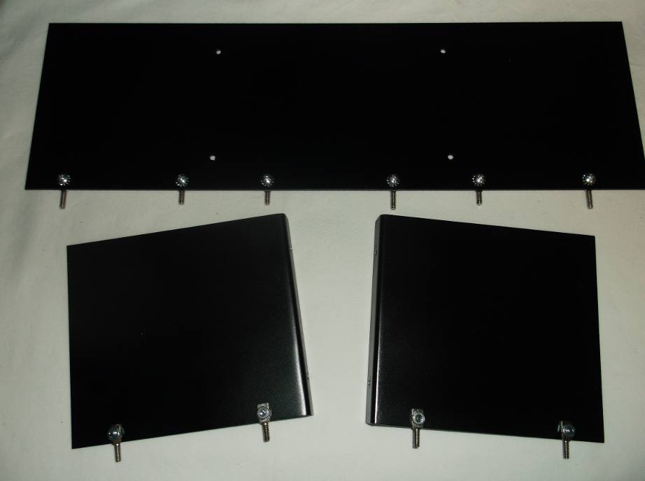
I acquired some sheet aluminum panels cut to size from a local welding shop for RF shielding, two(2) pieces measuring 5×4.5 in. have a 1/2 in. lip at one end, bent at a right angle, to attach to a larger 14×4.5 in. panel that runs along the middle of the chassis behind the RF stages. While I contemplated using a lighter steel material, the heavier aluminum will help to stiffen the chassis a bit.
I started painting these panels, one side at a time on consecutive days. The pieces were lying flat atop small pieces of wood on a covered table on the backyard porch. However, I discovered an unforeseen problem when gathering the pieces to bring into the house before dark on the second day:
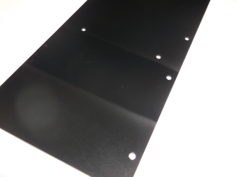
The mist created by the paint stream had coated the underside that was previously painted, causing a milkish appearance where the panel was not setting on blocks. To resolve this, I hung the pieces from wire and re-painted both sides. They turned out much better, shown below with spade lugs attached ready for mounting to the chassis:
The BFO can and one (1) IF can were torn down to replace the grid leads with cloth covered wire (18 AWG) and larger grid clips, as the originals were sized for 6J7/6K7s. The original wires coming out of the bottom of the cans were also replaced with cloth covered wire (20 AWG). The 50K grid leak resistor in the BFO can was also replaced with a 100K carbon resistor for use with a 6C6 (or 57) BFO tube:
Amongst other items added to the chassis were a 100mH shielded RFC for the detector plate filter, grid leads / clips for the RF preselector and 1st detector tubes, the grid components (100K, 100pF) and grid lead / clip for the HFO, and various connectors at the rear (antenna BNC, 4-pin accessory jack, 1/4 in. mono audio jack) and a hole w/ rubber grommet to feed the power cable through:


