Crystal Filter
The crystal filter unit came from a parted HRO-7. It is essentially the same circuit as that of a late model HRO-5TA1 with a 6-position selectivity switch and variable phasing control; earlier HROs (and FB-7 superhet) had a variable capacitor for selectivity control instead of discretely switched selectivity.
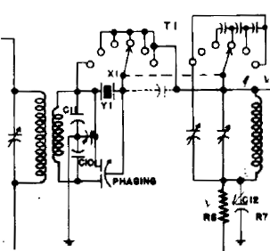
As with the BFO and IF cans, the crystal filter unit was disassembled to replace the original leads with cloth covered wire. Those exiting below the chassis are 20 AWG and the grid lead to the first IF amplifier is 18 AWG. While not complicated to work on, disassembling this unit is tedious. There are two (2) round cans inside the enclosure that house the input and output transformers. From each of these cans exit four (4) leads through small holes in the cans. Some leads exit the unit while others connect to filter components within the enclosure. Sliding the “guts” out of the cans requires care.
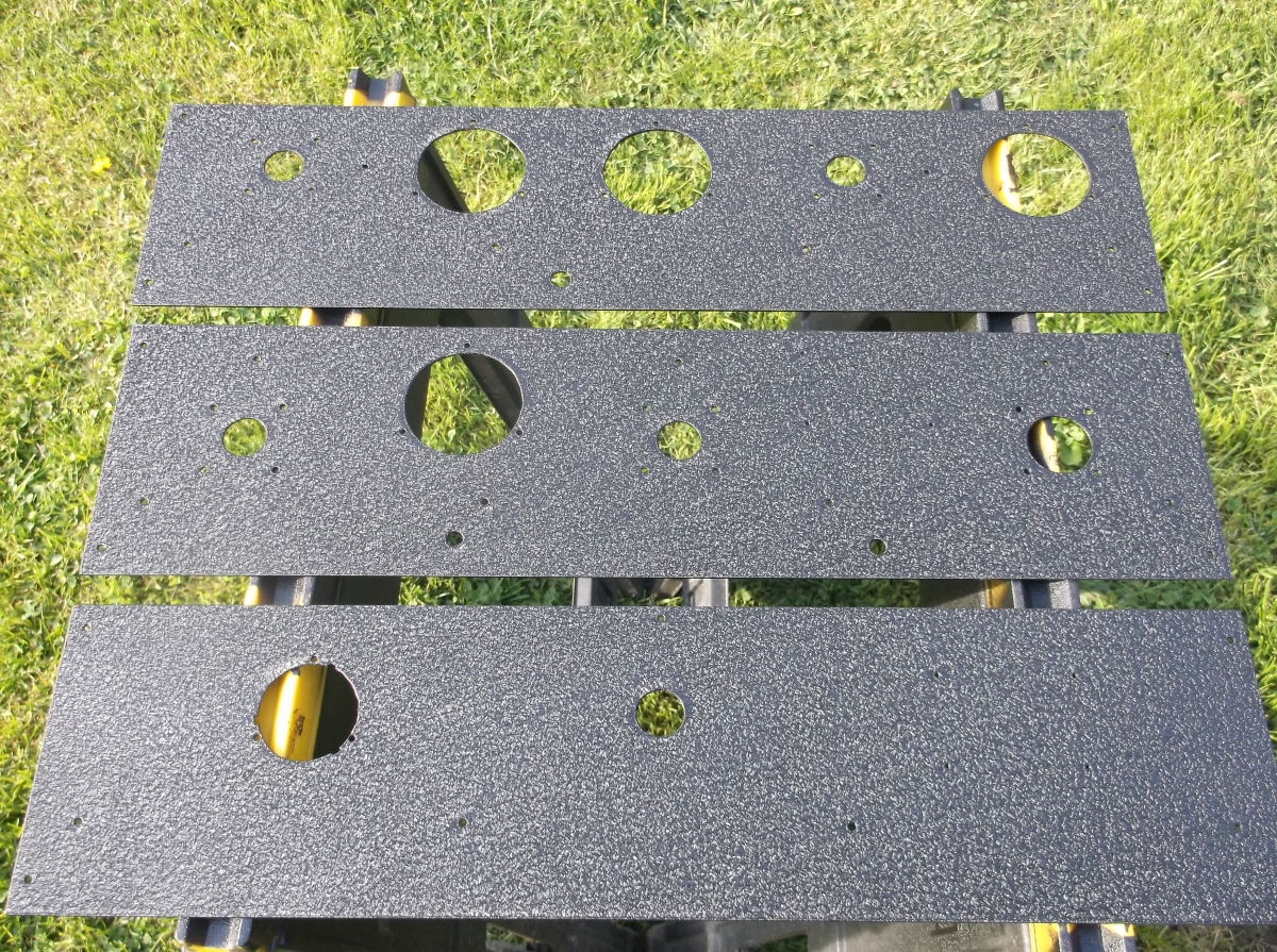
The enclosure was also painted satin black to match the finish of the chassis.
After re-assembly and painting, the unit was installed at the front right of the chassis. There are five (5) mounting studs. A 1-3/8 in. hole was also punched in the chassis where the input leads exit the bottom of the filter unit, so as to also have access to the tuning capacitor if tuning of the input tank should ever need adjusted.