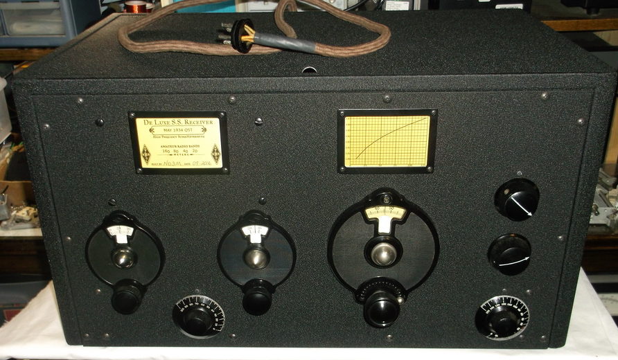
After experiencing some undesirable receiver behaviors during a station demo at the Breezeshooters Hamfest, I decided to dig into the homebrew 1934 superhet to try and resolve the issues as well as try some improvements. The receiver was knocked far enough out of alignment during the trip to the hamfest to cause one of the IF tubes to break into oscillation when the gain control was advanced to a certain point. That was easy enough to fix with a complete re-alignment.
Another annoying issue was an intermittent “raspiness” that would develop on CW notes. Perhaps a bad solder joint, dirty tube socket wipers, etc. Ultimately, this particular problem was resolved while troubleshooting another issue that I hadn’t noticed before. When I powered up the receiver on the bench after returning home, I noticed a very high pitched note (perhaps 10-12 kHz) in the audio. In trying to identify the source, I touched the grid cap of each tube. The signal stopped when I got to the BFO tube. After swapping in a different 57, the high pitched note was gone. Subsequently, so was any further intermittent raspiness.
There were a number of improvements I decided to implement while I had the rig on the bench. I added a 8uF/450V cap at the junction of the rectifier (80) output and filter choke in the power supply, converting it to capacitor input. This increased the supply voltage under load from 200V to 260V. The receiver seemed to have more “pep” with the additional voltage.
The gain potentiometer I originally installed had always been a bit “noisy”, had a limited useful range, and when approaching maximum gain, would have an effect on the HFO frequency (changing the CW pitch). There were several concurrent improvements made to resolve these issues. In the original circuit, the gain pot was actually part of the main voltage divider which is tapped to provide lower voltages where needed. Altering the gain control resistance would have a larger than desired effect on those tap voltages, so I isolated the gain pot to it’s own circuit using a 100K bleeder resistor to B+. The original voltage divider was then grounded through the last resistor in the chain, which was a 22K/2W changed to a 24K/2W. The gain pot itself was changed from a 5K unit to a 12K from a parted HRO-7. The new pot was quiet and has an optimal taper that increases it’s useful range.
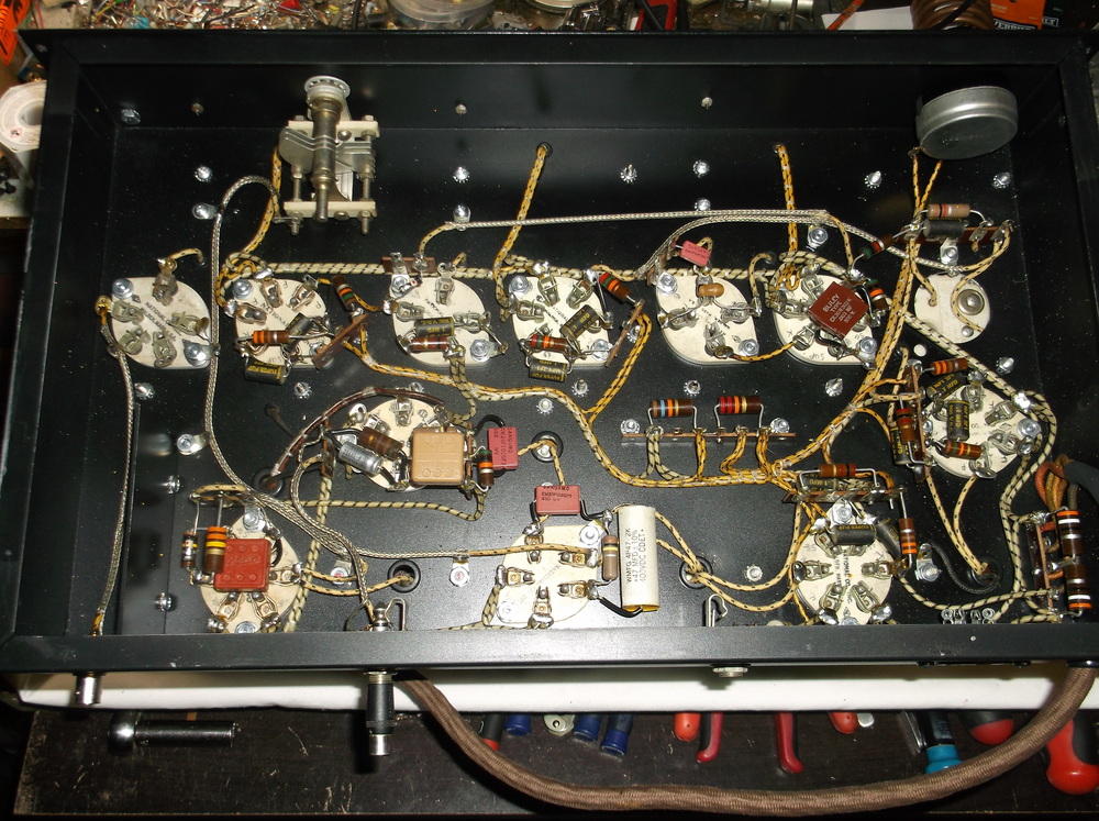
To limited gain change effects on the HFO, I also converted the 1st IF from being variable gain to fixed gain by directly grounding it’s cathode resistor. This would keep a constant input impedance on the 1st mixer which in turn would give a consistent load to the HFO, reducing any effects on it’s frequency. To some extent, the above voltage divider improvements also reduced voltage excursions to the HFO’s plate and screen, additionally aiding in stability.
Lastly, I made some changes to the gain distribution of the receiver by adjusting the bias on a couple tubes. The 1st IF cathode resistor was increased form 300 ohms to 1K (reduce gain). The 1st mixer cathode resistor was decreased from 25K to 5K (increase gain). While I haven’t experienced any IF oscillations after the re-alignment, the lowered gain in the IF should further help to prevent them in the future.
Much of the above was based on circuit variations of similar superhets published in 1934/1935 QST articles. This lineup of tubes and basic superhet design was pretty much the standard in the mid-30s. Not only common amongst homebrewers, but basically the same as a National FB-7, original HRO and other commercial receivers of the time.
The combination of all these circuit changes has resulted in what almost feels like a different and much more well behaved receiver in terms of stability and usability.