Wiring, Smoke Test, Alignment
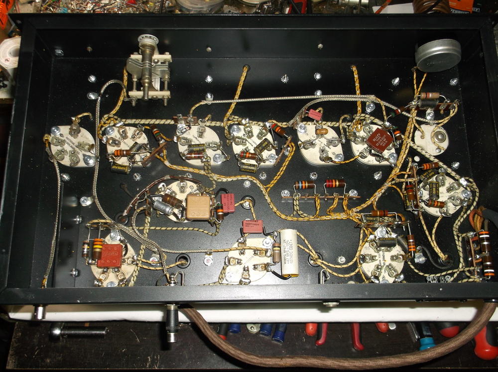
The construction process continued with wiring the underside of the chassis. I acquired NOS lacquered, cloth covered wire in several different gauges. All components (carbon comp. resistors, caps, etc.) are NOS, mostly 50/60s vintage. Wide, waxed covered, white dental floss was used for lacing the wire bundles where needed. In commercial gear with wire harnesses, lacing was generally done first, then the harness installed. For this one-off homebew project, I just laced the wire bundles in-place after installation.
I initially wound a coilset for 160M. The required inductance for the grid circuits of the RF pre-selector and 1st detector was calculated based on the variable capacitors used, in this case, National ST-75s, with a maximum capacitance of 75 pF. Resonating with 65pF capacitance would require 120uH inductance. Hammarlund 1.5 in diameter, ribbed coil forms were used. 68 turns over 1.5 in. of the form provided the 120uH needed. The primary winds of each coil (ie. antenna coil and pre-selector plate coil) were wound per a 1935 QST article of a similar receiver, as 160M coil data was not published in the 1934 article this receiver was based upon.
The HFO (oscillator) coil was a little more complicated. I decided to pad the circuit with a 49 pF NPO fixed capacitor and install a APC trimmer (80pF) inside the coil form for band setting. I found a handy note in another QST article from the 30s that made the following statement about band spreading in relation to the tap on the coil , “the effective capacitance is equal to the square of the percentage of the coil where the tap is located.” As an example, a 50pF bandspread capacitor connected to a coil tap in the middle (ie. 50%), would have an effective maximum capacitance of (0.5 ^ 2) * 50, or 12.5 pF. I found this rough calculation to be a reasonably good prediction in practice. Of course, there are other factors to consider in relation to the tap such as linearity, etc., that can have an impact on the effectiveness of tracking if multiple stages are ganged, but since I chose to tune each stage individually, I was not concerned with those effects.
The HFO is tuned approx. 456 kHz higher than the signal to be detected, based on the IF frequency of the re-purposed HRO crystal filter and cans. To calculate the approximate required inductance, I chose a mid-high value for the bandset (trimmer) of about 60pF. Added to the 49pF NPO, I would need about 45.7uH of inductance. On a 1.5 in. Hammarlund form, this equates to 42 turns spaced over 1.5 in. I wanted the 50pF tuning capacitor to cover a range of about 90-100 kHz on 160M. Based on the resonant circuit above (109pF + 45.7uH), I calculated the approximate change in capacitance required for 1 kHz frequency change. That value was multiplied by the desired range to find the needed capacitance range. That capacitance was divided by 50 pF (tuning capacitor) and the square root taken. The final result is the percentage of the coil where the bandspread tap is located, in this case, ending up at 18 turns from the cold end. Finally, a cathode return tap between 25 – 35% would be needed, decidedly at 11 turns from the cold end.
After the HFO coil was wound, all coils were plugged into their respective sockets. With everything being wired, 2.5 VAC tubes were plugged in and the receiver “smoke tested”. The filament voltage at the radio was rather low, only about 2.0 VAC. The voltage at the power supply end was only about 2.4 VAC, the filament transformer was a little too light for the required current. Once I find a heftier filament supply for 2.5 VAC, even the 0.4 VAC drop across the receiver’s supply cable should be manageable, since the transformer secondary voltage will probably end up around 2.8 – 3.0 VAC due to high AC line voltage (120VAC vs. 110VAC that most transformers are rated for).
In the meantime, I installed equivalent 6.3VAC tubes (6C6, 6D6, 76, 42) and fired up the receiver. I initially wound a coilset for 160M. The receiver was pretty much dead, not even an indication of internal / receiver noise. Of course, it probably needed aligned! I consulted numerous documents on alignment procedures and eventually made an outline based on the various sources, founding the methods outlined in the HRO series manuals to be the most useful, particularly some comments in the HRO-60 manual. Below is the outline of the process taken from my lab notes:
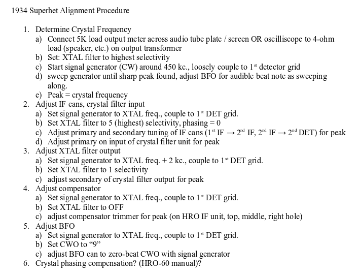
This procedure ended up being quite effective, at least it seemed that way with a test signal and no antenna connected. Now it was time to see if it could receive on-air signals…..