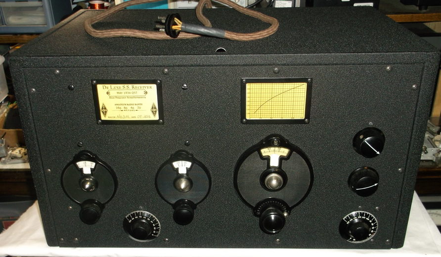
Front Panel Embellishments
The final touches on the front panel were installed today. Dial markers were added just above the BFO, RF gain, and crystal filter phasing control knobs. The markers were made by filing down the heads of #2-56 screws. These are similar to the dial markers used on the National HRO series receivers.
Next, an information tag and main tuning calibration chart were added. The hi-resolution (300dpi) graphics were created in GIMP (GNU Image Manipulation Program). The calibration charts (160, 80, 40, 20) were modelled after the early HRO style paper charts that were on the plugin coilsets, with a 0.1 in. grid. In fact, the satin-black metal frames and clear plastic covers (yellowed from age) to mount the information tag and calibration chart were taken from an old HRO coilset. The frames are held in place with #4-40 black screws. The front panel has tapped holes to accept the screws. When changing bands, the calibration chart above the main tuning dial can be changed by removing the top screws and loosening the bottom screws. The charts can be slide in and out from the top.
The yellowing of the plastic covers really adds a nostalgic appearance to the receiver.
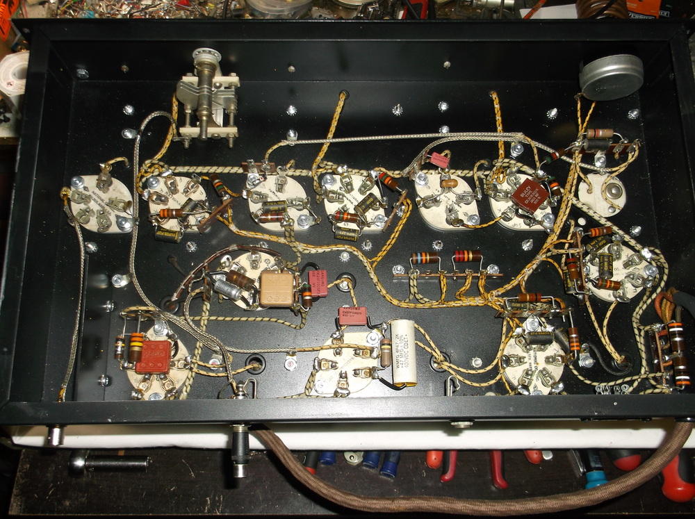
With all of the front panel work complete, it’s time to start wiring!