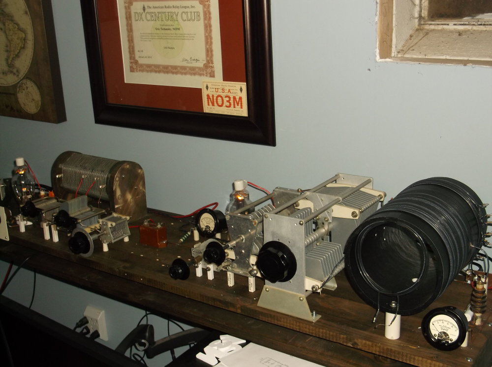
630M MOPA (Master Oscillator – Power Amplifier) consists of an 809 “High-C” Hartley capacitively coupled to a push-pull power amplifier, either running 809s or 811s.
Power output is on the order of 100-165W with 1600V on the amplifier tube plates. CW note is clean and stable (slight chirp reported over the air).
Recording: 630m-MOPA-single-2014-10-22-2.mp3
 (note: single ended amp circuit shown above prior to modifying to push-pull)
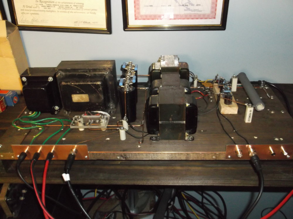
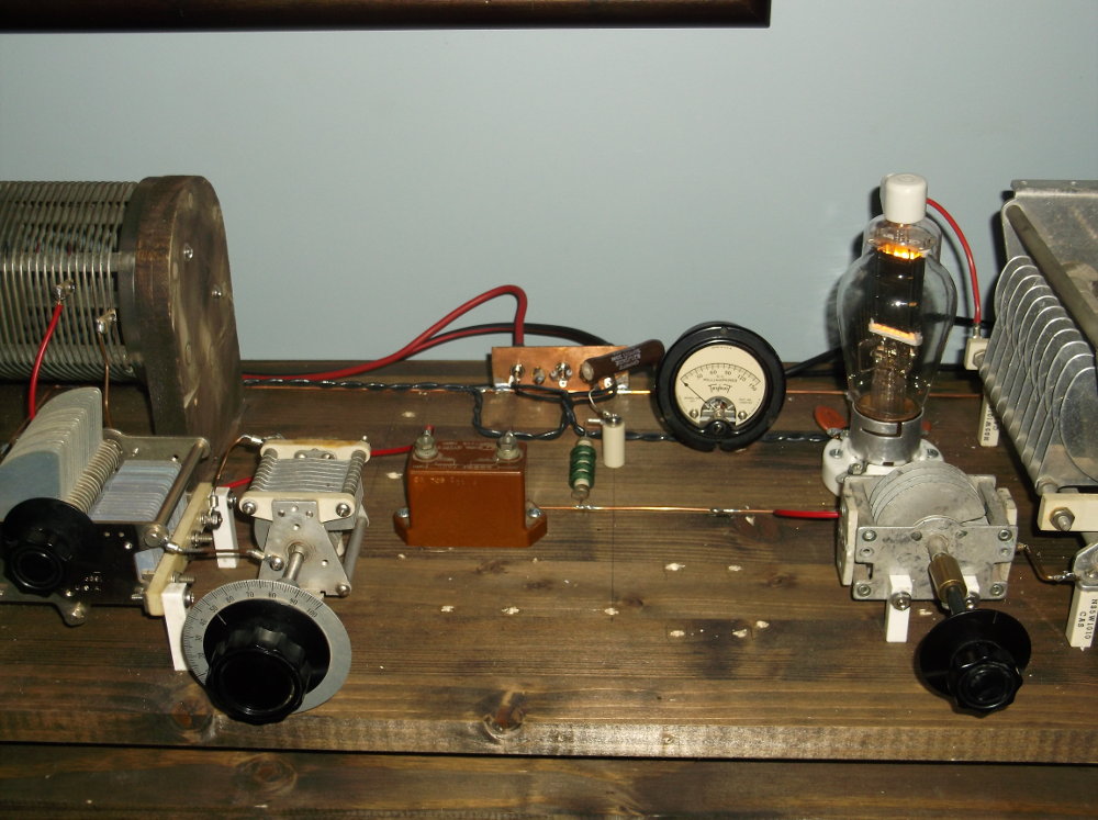
6.3VAC @20A; 1600V full wave, center tapped, choke input; 1000V Bridge rectified, choke input, with 25K ohm / 100W loading resistor, 500V from transformer center tap.
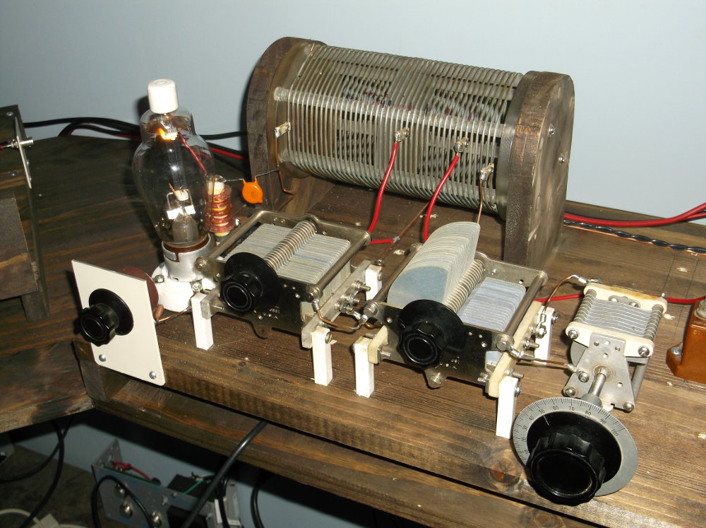
High-C Hartley oscillator using an 809 triode at 1000VDC plate voltage. Grid leak set at approx. 15-25K ohm. Plate tank coil is a recycled bugcatcher mobile coil with wooden sidemounts added.
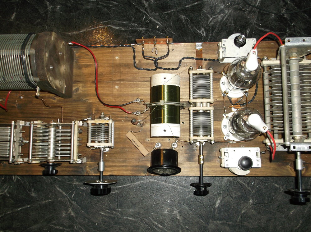
Interstage coupling is accomplished with a 2 turn link on the grid end of the Hartley oscillator coil (black insulated wire around coil on left) and a 2 turn airdux coil around the amplifier’s grid coil. The push-pull amp grid coil is approx 250 turns of #28 enameled wire on a 2.5 inch form.
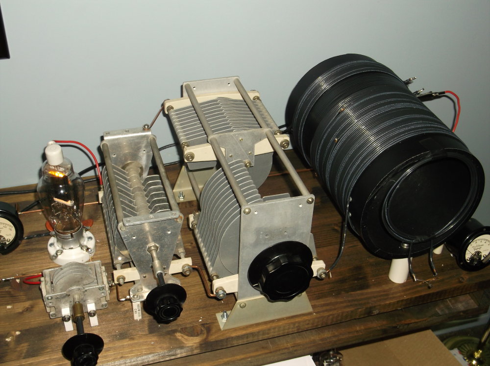
The amplifier stage is a self-biased 809 with 1600V on the plate. The plate tank is 535uH, center-tapped for B+ through a 4-5uH RFC. The tank circuit is resonated with a single-section 100pF 4.5kV variable in parallel with a split-section, 300pF/sec. 4.5kV variable capacitor. The rotors of the split-section variable are grounded and each stator section connected to either end of the tank coil, which balances the RF potential in the coil, resulting in equal amplitude but opposite phase RF at opposite ends. This serves to provide a convenient place to connect the neutralizing capacitor (to the end opposite the plate connection) without resorting to additional coil taps. There are also additional benefits to a balanced tank (see QST, January 1934, “Improving the Performance of the Neutralized Power Amplifier”, George Grammar). One end of the tank is connected to the tube anode, the other end is connected back to the tube’s grid via a 25pF variable neutralizing capacitor.
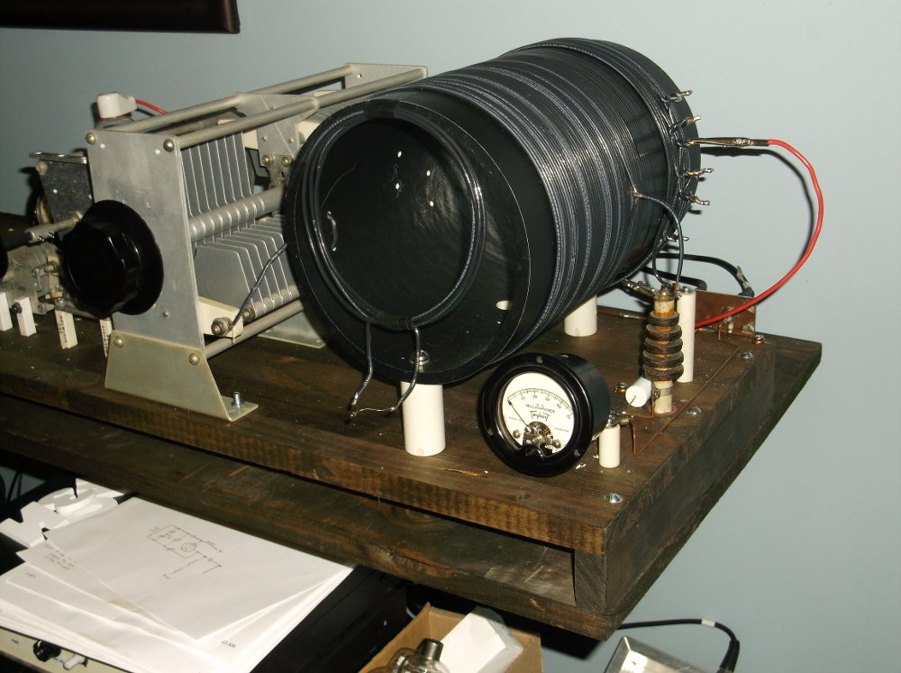
Antenna coupling is accomplished via a 10 turn winding over the tank coil (seen on the far-end of the tank coil. Generally links are at the “cold” end, which is at the center of this tank coil, but winding over an end was chosen more for convenience). Each turn is tapped after the fourth turn, providing a convenient way to adjust coupling as needed. A 3-4 turn, loosely coupled pickup coil with a light bulb is shown dangling from the front (attached with tape) as a visual indication for neutralization and is not used under normal operation.
=======
Previous Interstage Coupling with Single-ended Amplifier circuit
Sangoma 5kV 200pF mica capacitor ($1 hamfest find) is used to couple the oscillator and amp stages. A tap off the oscillator coil is selected for minimal oscillator interaction while maintaining adequate drive for the amplifier. Amplifier stage (809 triode) uses grid leak bias via a 5K ohm 10W resistor, seen along with an RFC and grid current DC ammeter.