Classic Hartley transmitter using an 811 tube. Aprrox. output 45-65W (depends on coupling).
Rig is mounted on a 21 in. L x 18 in. deep board, cut from a 48×18 prefabricated, edge-glued shelf board from big-box home improvement store. Stained with dark walnut finish.
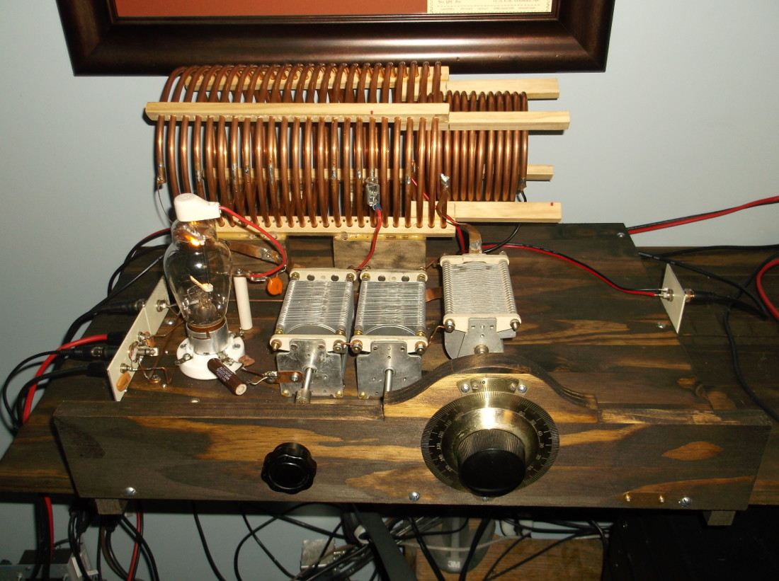 National Velvet Vernier used with 500pF tuning variable. Two (2) additional air variables (1000pF ea.) are required to resonate the oscillator in the 630M band. The main tuning coil is approx. 45 uH and constructed of 1/4 in. copper tubing. Spacers for the main coil where made out of strips of hobby wood, drilled with holes and after forming the copper tubing coil, it was fed through the spacers (takes patience as spacers can get tough to slide once half the coil is threaded!)
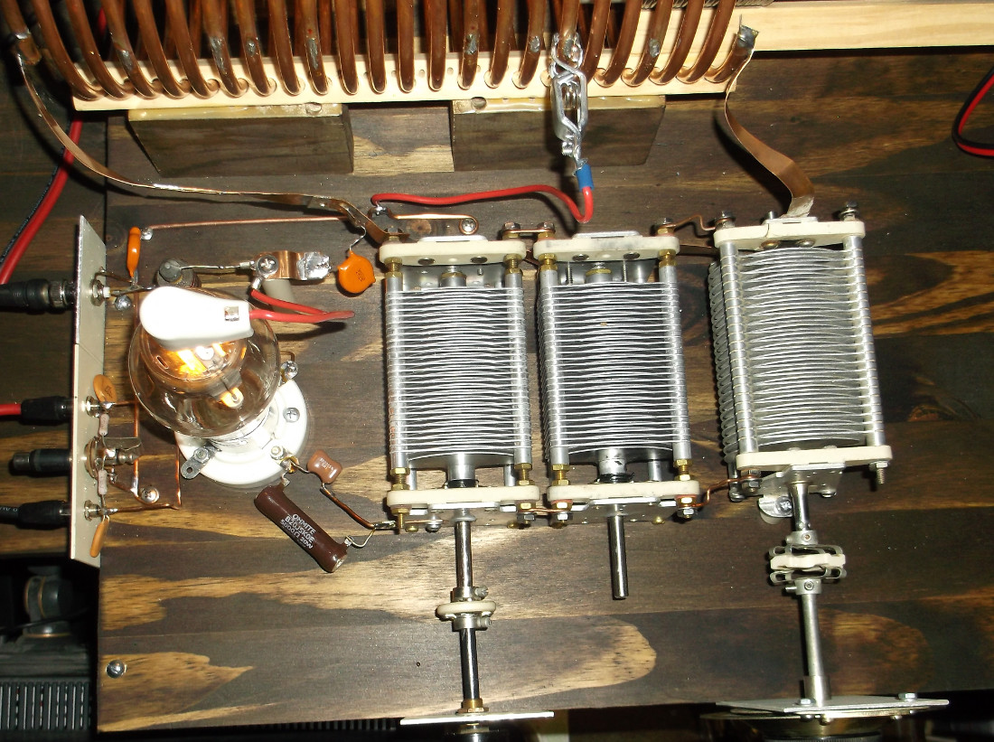 Overhead view of rig, showing tuning caps, grid feedback compnents, main coil ground (B-) tap.
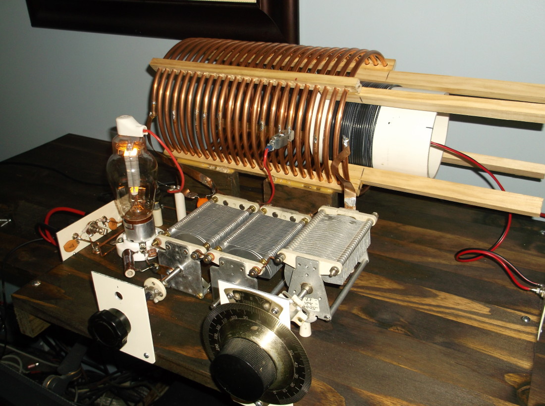 The test antenna coupling coil is composed of 22 turns of #14 THHN insulated wire wound around a 4 inch piece of PVC. The coil can slide along the wooden “rails” that were glued to the main coil wood spacers. #16 hookup wire is soldered to the coil ends inside the PVC and exits the end opposite the main coil, soldered to an RF connector on the right. The antenna coil pictured above was later replaced with a copper tube coil as seen in the first photo at the top of the page.
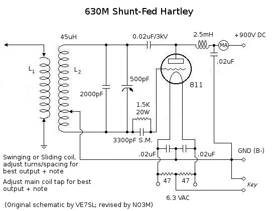
(note: grid feedback resistor and fixed capacitor may not reflect final values, pending experimentation)